Contour lines
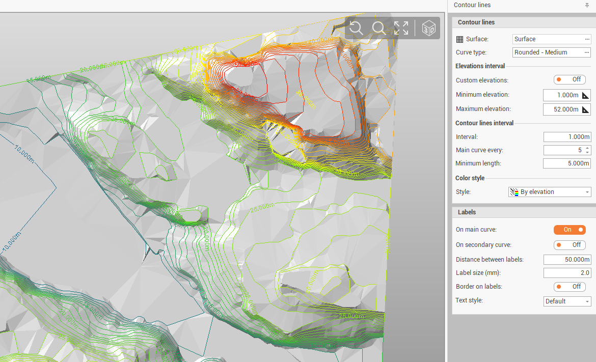
X-Pad Office Fusion is able to calculate, based on a reference surface, the contour lines and also to manage the insertion of the labels.
This allows to understand the elevation variations of a surface and its morphology more simply than the triangular model.
To generate the contour lines must have been generated the reference surface, then the program is able to create the contour lines.
Click Surfaces.
Click Generate.

This command opens a panel on the right where to enter the contour lines parameters.
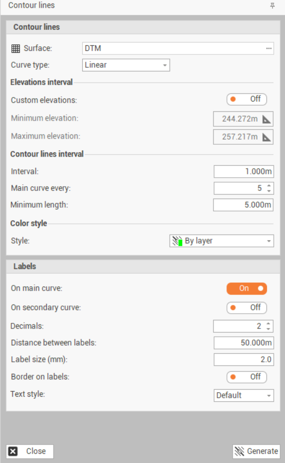
Surface: sets the Surface subproject in which to perform the processing.
Curve type: sets the type of curve to create:
Linear: the contour lines are lines lying on the triangle surface.
Rounded - Low: the contour lines are rounded with a small factor of rounding.
Rounded - Medium: the contour lines are rounded with a medium factor of rounding.
Rounded - High: the contour lines are rounded with a high factor of rounding.
Custom elevations: toggles the use of the custom elevation range for creating contour lines. This allows to create the contour lines only in a part of the entire surface.
Minimum elevation: sets the minimum elevation value to generate the contour lines, if the custom elevation range usage is enabled. Clicking on the button you can select the elevation in the CAD window.
Maximum elevation: sets the maximum elevation value to generate the contour lines, if the custom elevation range usage is enabled. Clicking on the button you can select the elevation in the graphics view.
Interval: sets the elevation range with which the contour lines will be generated.
Main curve every: sets the elevation range of main contour lines. The main curves are generated on a specific layer other than the secondary layer curves.
Minimum length: the minimum length to create a contour line, to avoid contour lines too short.
Style: sets the color mode of the contour lines. Options can be:
By elevation: The contour line uses the color scale set according to the elevation.
By layer: The default color setting of the contour lines is used based on the layer.
On main curve: toggles the display of the elevation label on the main curves.
On secondary curves: toggles the display of the elevation label on the secondary curves.
Decimals: number of decimals for labels.
Distance between labels: sets the distance between labels along the contour line.
Label size (mm): sets the size of the labels in mm. The size changes depending on the scale.
Border on labels: enables/disables the label border design.
Text style: allows to select the label style from available text styles.
Click Generate to generate the contour lines.
To show/hide the generated contour lines, you can activate/deactivate the Contour lines entity in the Filters.
Add label
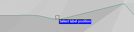
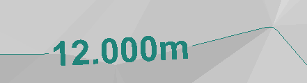
The command Add label allows to manually add a label on selected contour line on the specified position.
Click Surface.
Click Add label.

Click in the CAD on a contour line to add the label.
Remove label
The command Remove label allows to delete a contour line label.
Click Surface.
Click Remove label.
Click in the CAD on a contour line label to remove it.