Skip table of contents

Point

Use the command Point to draw topographic points, according to different methods.
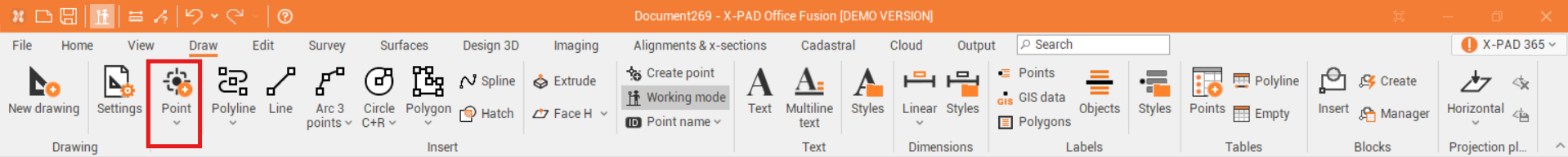
  • Point.

  • Coordinates.

  • Azimuth & Distance.

  • Distance & Offset.

  • Intersection.

  • Projection to entity.

  • Add to entitis.

  • Delete from entities.

  • Divide.

  • Measure.

  • From block’s reference.

  • From mesh vertices.


Point

Use the command Point to create a point to the current survey subproject in the graphic view.

  • Click Draw.

  • Click Point.

  • Click on graphic view to create the topographic point.

    • You can enable/disable object snap.

      image-20241127-171044.png
    • You can edit the point name, and point coordinate from Point position bar.

      image-20241127-171142.png

Po

Points can be entered manually:

  • Click on Survey.

  • Click Points and select the Survey subproject.

    image-20250115-094853.png
  • From the new window, click on image-20250115-095129.png and enter the name and coordinates of the new point you want to add.

  • click on OK once you finish.

    image-20250115-095349.png
  • They can also be added from the Points list, directly by entering the point’s information in the corresponding fields.

    image-20250115-095942.png

Coordinates

Use the command Coordinates to create a point to the current survey subproject entering the point coordinates.

  • Click Draw.

  • Click under Point to open the drop-down menu.

  • Click on Coordinates.

  • This function opens a table on the right side of the window.

    image-20241127-171342.png
  • Enter the requested information to create the topographic point.

    • Type: selects if point is a User point or a Reference point.

    • Name: the name ID of the point.

    • Survey code: selects the survey code to assign to the point from the list of Survey code assigned to the project.

    • Description: the point description.

    • Position: the position in E,N,Z.

    • WGS84: turns on WGS84 option to activate the WGS84 coordinate for the point. It is possible to edit the WGS84 coordinates and E,N,Z are recalculated. A cartographic system assigned to the project is required.

  • Or click on the graphic view to create the point graphically.


Azimuth & Distances

Use the command Azimuth & Distance to create a point to the current survey subproject entering azimuth/bearing and distance from a reference point.

  • Click Draw.

  • Click under Point to open the drop-down menu.

  • Click on Azimuth & Distances.

  • This function opens a table on the right side of the window.

    image-20241127-171700.png
  • Enter the requested information to create the topographic point.

    • Type: selects if point is a User point or a Reference point.

    • Name: the name ID of the point.

    • Survey code: selects the survey code to assign to the point from the list of Survey code assigned to the project.

    • Description: the point description.

    • Reference point: selects from point list or on the graphic view the reference point.

    • Azimuth/Bearing: the azimuth/bearing from the reference point.

    • Distance: the distance from the reference point.

  • Or click on the graphic view to create the point graphically.


Distance & Offset

Use the command Distance & Offset to create a point to the current survey subproject entering the distance and vertical offset from an object or a line identified by 2 points.

  • Click Draw.

  • Click under Point to open the drop-down menu.

  • Click on Distance & Offset.

  • Select a drawing object or select the initial and final point of the line.

  • Enter the Distance and Offset to create the point. The distance can be entered in the bottom bar, or graphically.

    image-20241127-173258.png

Intersection

Use the command Intersection to create a point in the intersection of 4 topographic points or drawing objects. It is also possible to define an offset.

  • Click Draw.

  • Click under Point to open the drop-down menu.

  • Click on Intersection.

  • Select the first couple of topographic points or the first drawing object.

  • Enter an offset (optional).

  • Select the second couple of topographic points or the second drawing object.

  • Confirm the proposed solution to save the new topographic point.

    image-20241202-170217.png

Projection to entity

Use the command Projection to entity to create a topographic point by projecting selected point on a selected drawing entity.

  • Click Draw.

  • Click under Point to open the drop-down menu.

  • Click on Projection to entity.

  • Select topographic point to project.

  • Select the entity to which project the point.

    image-20241203-083339.png
  • Click to create the point.


Add to entities

Use the command Add to entities to create a topographic points to main position of selected entities.

  • Click Draw.

  • Click under Point to open the drop-down menu.

  • Click on Add to entities.

  • Select objects to which add topographic points. Can be directly selected in the graphic view clicking on them, or with a selection area. Or can be selected using the commands int he bottom part of graphic area.

    image-20241203-083816.png
  • Confirm the selection to create the points.

    image-20241203-083915.png

Delete from entities

Use the command Delete from entities to delete topographic points from the main position of selected entities.

  • Click Draw.

  • Click under Point to open the drop-down menu.

  • Click on Delete from entities.

  • Select objects from which delete topographic points. Can be directly selected in the graphic view clicking on them, or with a selection area. Or can be selected using the commands int he bottom part of graphic area.

    image-20241203-084129.png
  • Confirm the selection to delete the points.

    image-20241203-084214.png


Divide

Use the command Divide to divide selected reference objects in parts and create topographic points. Reference objects can be a lines, polylines, arcs and circles.

  • Click Draw.

  • Click under Point to open the drop-down menu.

  • Click on Divide.

  • Select objects to divide. Can be directly selected in the graphic view clicking on them, or with a selection area. Or can be selected using the commands int he bottom part of graphic area.

    image-20241203-131443.png
  • Enter the number of parts.

  • Confirm to create the topographic points.

    image-20241203-131549.png


Measure

Use the command Measure to add topographic points at fixed distance along a reference object. Reference objects can be a lines, polylines, arcs and circles.

  • Click Draw.

  • Click under Point to open the drop-down menu.

  • Click on Measure.

  • Select objects to divide. Can be directly selected in the graphic view clicking on them, or with a selection area. Or can be selected using the commands int he bottom part of graphic area.

    image-20241203-131729.png

  • Enter the distance. Distance can be entered:

    • Measure distance: measures the distance to use on the graphic area.

    • Enter value: enters the distance manually.

    • Only on vertices: the topographic points are created only on the vertices of selected objects.

  • Confirm to create the topographic points.

    image-20241203-131957.png


From block’s reference

Use the command From block’s reference to convert selected block’s reference to topographic points. Attribute’s values can be used to extract the name, elevation and code of extracted points.

  • Click Draw.

  • Click under Point to open the drop-down menu.

  • Click on From block’s reference.

  • The function opens a panel on the right of the graphic view.

    image-20241203-142146.png
  • Select the options to convert the blocks:

    • Block name: selects the block from the list to convert to topographic points.

    • Drawing (source): selects the drawing sub-project where there are the blocks.

    • Select block references: if enabled, allows to select from the graphic view the blocks to select. If disabled, all blocks are selected.

    • Delete block references: if enabled, deletes the blocks when they are replaced by topographic points.

    • Survey (destination): selects the survey sub-project where the points will be created.

    • Next point name: selects the name ID of the first created point.

    • Block’s attribute: if enabled, block attributes can be used to extract point name, elevation and code.

      image-20241203-142746.png
  • Click Apply to create the topographic points in the selected Survey subproject.

    image-20241203-142916.png

From mesh vertices

Use the command From mesh vertices to create topographic points on the selected mesh vertices.

  • Click Draw.

  • Click under Point to open the drop-down menu.

  • Click on From mesh vertices.

  • Select the mesh. Can be directly selected in the graphic view clicking on them, or with a selection area. Or can be selected using the commands int he bottom part of graphic area.

    image-20241203-143306.png
  • Confirm the selection to create the topographic points.

    image-20241203-143401.png

JavaScript errors detected

Please note, these errors can depend on your browser setup.

If this problem persists, please contact our support.