Project settings
Define different parameters and options for the current project.
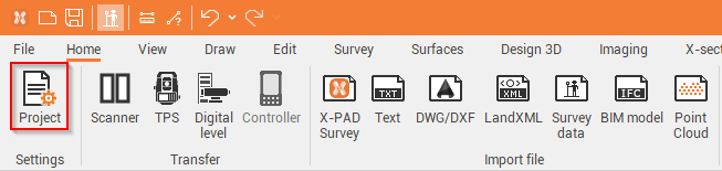
Click Home.
Click Project.
To save these settings as default for new projects, see Creating a project template
Drawing
Sets the drawing’s scale, used for plotting or for exporting to DWG/DXF of the plotting preview. The size of the labels and the symbol of the points is calculated based on this value.
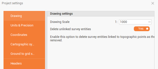
Drawing scale: defines the scale of the drawing that is used for plotting or exporting DWG/DXF.
Delete unlinked survey entities: allows to delete the survey entities that are linked to the deleted topographic points.
Units & Precision
Defines the type for measurement unit and the precisions.
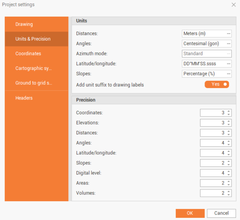
Units: allows to define the unit used in the software.
Distances: the unit used for distances.
Angles: the unit used for angles.
Azimuth mode: the mode used to display the azimuth. Bearing can be selected if the angle is DDàMM’SS.ssss unit.
Latitude/longitude: the visualization mode for latitude and longitude.
Slopes: the unit used for slopes.
Add unit suffix to drawing labels: all values reported by the software in the drawings include a suffix indicating the unit of measurement - this applies to distances, elevations, and angles. This option allows to report values without the unit suffix. This setting affects both drawing labels and in all export formats (ASCII, DXF/DWG, etc.).
Precision: allows to customize the precision of different measure values.
Coordinates: precision for coordinate values.
Elevations: precision for elevation values.
Distances: precision for distance values.
Angles: precision for angle values.
Latitude/longitude: precision for latitude and longitude values.
Slopes: precision for slope values.
Digital level: precision for digital level values.
Areas: precision for area values.
Volumes: precision for volume values.
Coordinates
Defines the label used by the program to represent the coordinates of the abscissas (X), ordinates (Y), and elevation (Z) and the order in which the coordinates will be displayed.
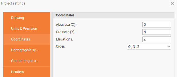
Absissa (X): the label used to represent the coordinates of the abscissas (X).
Ordinate (Y): the label used to represent the coordinates of the ordinates (Y).
Elevations: the label used to represent the coordinates of the elevations (Z).
Order: the order in which the coordinates will be displayed
Cartographic system
Defines the coordinate system to be used in the project and its parameters. Allows to load a predefined system from the list of user-defined systems.
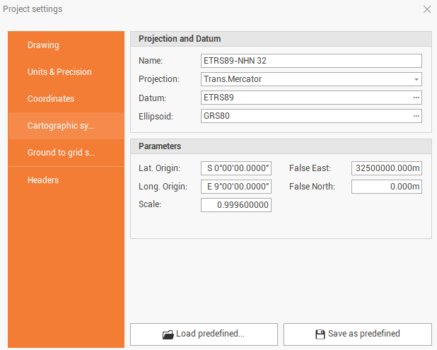
Lat. Origin: defines the latitude of the origin of the coordinate system.
Long. Origin: defines the longitude of the origin of the coordinate system.
Parallel 1: specifies the first parallel for the coordinate system.
Parallel 2: specifies the second parallel for the coordinate system.
Scale: sets the scale factor of the coordinate system.
False East: defines the coordinate for the false East of the coordinate system.
False North: defines the coordinate for the false North of the coordinate system.
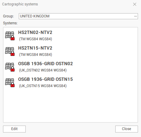
Load predefined: gives access to a list of predefined and user-defined coordinate systems.
Save as predefined: allows saving the parameters and settings of a coordinate system, to be used in other projects related to the same area.
Ground to grid
Defines the values and the parameters to reduce total station distances, from mean sea level to the cartographic plane.
The values set on this page are used in the survey calculations for Total stations (TPS).
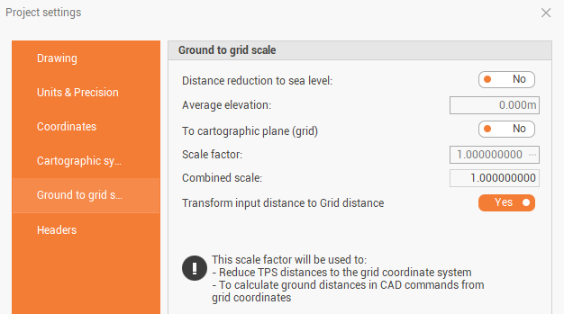
Distance reduction to sea level: enables/disables the use of parameters for calculating the reduction of distances to sea level.
Average elevation: value of average elevation used for distance reduction calculation.
Scale factor: enables/disables the reduction of distances based on a scale factor.
To cartographic plane (grid): scale factor for the distance reduction to the cartographic plane (grid). The value can be entered manually or calculated based on a coordinate. A coordinate system must be defined.
Combined scale: enables/disables the reduction of distances to both sea level and cartographic plane (grid).
Transform input distance to grid distance: enables/disables the use of parameters for the transformation.
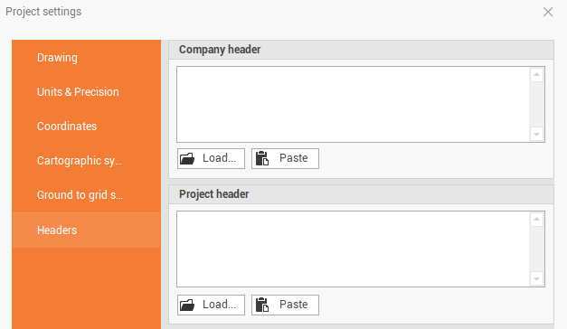
Headers
Defines the headers that appear in the printed outputs. The software allows you to import files in RTF format, Word files, images or to manually paste or write the header texts.