Skip table of contents

Subprojects

  • A project can contain different subprojects within the same category.

  • The data for each subproject is handled differently according to its type. Subprojects include both graphic data and attribute entities.

  • While working, a survey and design subprojects are active. The data is saved to these subprojects; for example, when drawing a polyline, it is saved in the active drawing subproject, and when inserting a topographic point, it is saved in the active survey subproject.

  • The Project Manager is the tool that helps to manage all subprojects in the workspace. Active subprojects are highlighted. in the Project Manager panel.

    image-20250102-093857.png

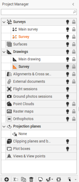
Subprojects categories are:

Subproject

Description

Survey

Holds data from the topographic survey.

  • Points: Imported coordinates from topographic instruments or other, for example GNSS bases, GNSS points, TPS points or TPS stations.

  • Reference points: Known coordinate points set during surveys or inserted later.

  • Measurements: Imported measurements from GNSS, TPS or PicPoint survey sessions.

  • Traverses: Traverses set during the work.

  • Level data: Imported and processed levelling data.

  • Survey drawing: Drawing entities linked to points.

  • Parcels: Cadastral parcels created through specific command.

Surfaces

Holds data from:

  • 3D models

  • Graphics

  • Analysis from volume calculations using surfaces.

The objects of this type are:

  • Break lines: Represent a surface interruption of the slope. It creates a mathematical model similar to reality.

  • Boundary external: The external boundary of the surface. Triangles are created inside the perimeter.

  • Boundary internal: The boundary lines that define an internal perimeter of the surface. Triangles are created outside this perimeter, allowing areas within the boundary to remain without triangles..

  • Triangles: Entities that form the surface

  • Contour lines: The contour lines are obtained from the generated surface.

  • Cut-Fill lines: These are the entities created by volume calculations, representing intersections between surfaces used in the calculation.

  • Design polylines: polyline created through 3D design.

  • Calculated volumes: Results from the volume calculation functions, stored in the subprojects.

Drawing

Holds graphic data, for example:

  • Imported DXF/DWG files

  • Specific drawings made by the program

Section groups

Holds:

  • Planimetric drawing of cross sections

  • Calculation results visible in the dedicated view

External references

External documents linked to the project, such as .ifc or .dwg files

Point Clouds

Display the connection to the file of the cloud data

Raster image

Holds background raster images that can be loaded into the
project. These images are linked to the project.

Orthophoto

Collects orthophotos used in the project. The images are only linked to the project.


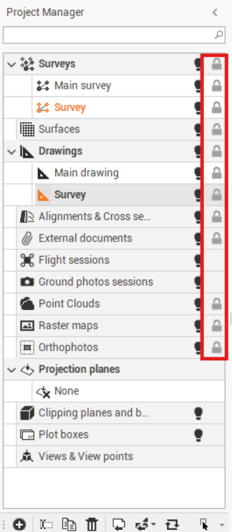
Locking a subproject

When a subproject is locked, its objects cannot be selected.

To lock/unlock a subproject:

  • From the project manager, navigate to the list of all subprojects stored in the job

  • Click on the lock icon next to the desired subproject, to active or deactivate it.

    image-20241007-114117.png

JavaScript errors detected

Please note, these errors can depend on your browser setup.

If this problem persists, please contact our support.