Create a surface
 + SURFACE&VOLUME |
  + SURFACE&VOLUME |
  + SURFACE&VOLUME
The Surface and Volumes module allows to create new surfaces automatically calculating the triangles based on the points available in the archive and on the defined breaklines. Or manually to obtain a result most to the real surface by improving the calculation results.
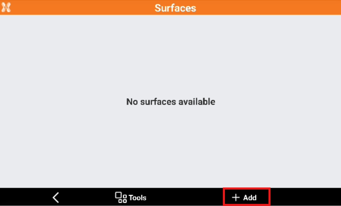
To create a new surface from the Surface and Volumes click Surfaces.
Click Add to create a new surface.
In the New surface page enter the new surface properties.
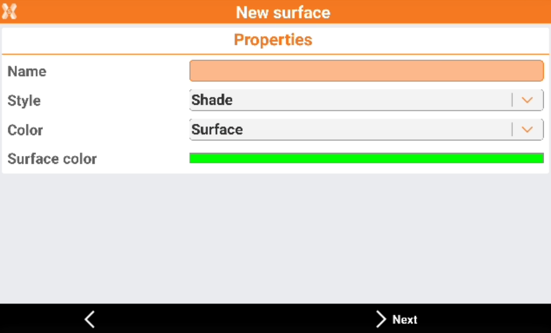
Name: name to assign to the surface.
Style: representation of the surface.
Wireframe: the segments of the triangles composing the surface are drawn.
Shade: the faces of the triangles are colored based on the direction of light exposure.
Color: color to use for the surface.
Original: the color of the layer containing the triangles is used.
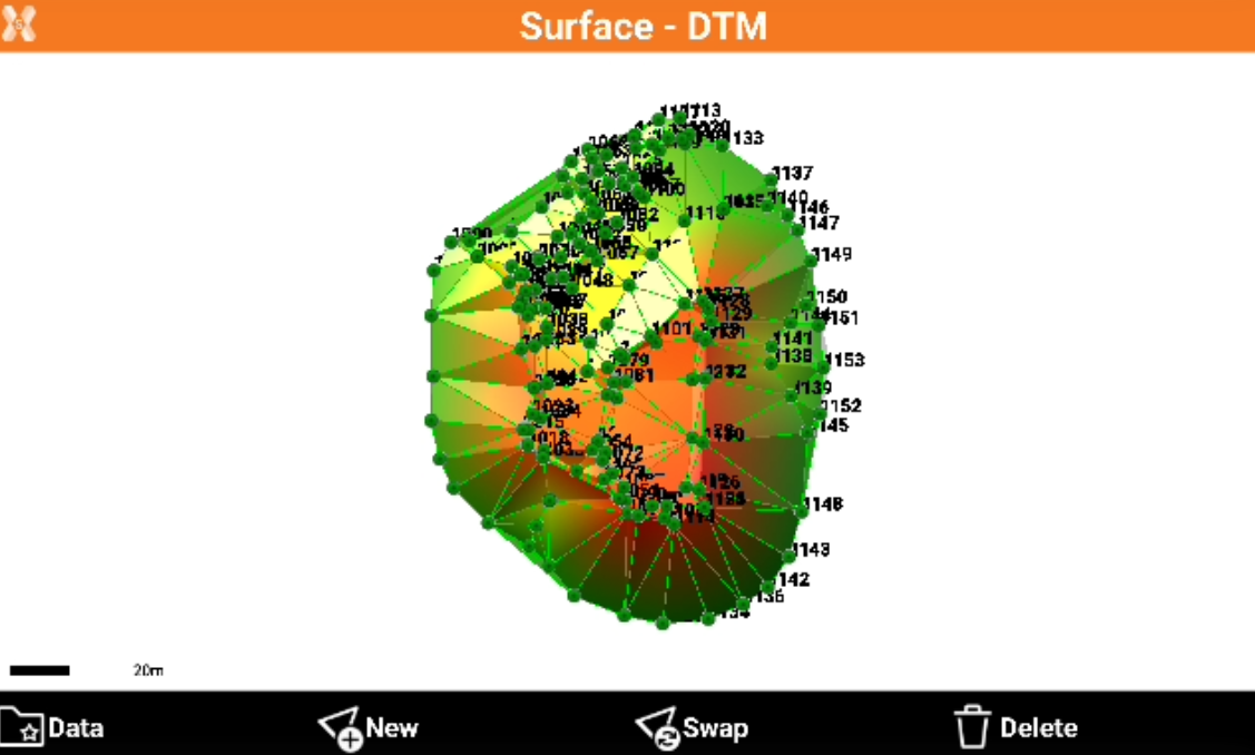
By elevation (terrain): the faces are coloured based on the elevation of the centre of gravity. The color scale starts from green, passes through yellow and ends with red.
Surface: a color can be defined in the field Surface color.
By elevation (sea): the faces are coloured based on the elevation on sea level. The color scale starts from green, passes through blue and ends with white.
Surface color: color to use for the surface if the option Surface is chosen.
Click Next.
In Points & lines page it is requested to define the triangulation mode and the elements that will be used to generate the surface.
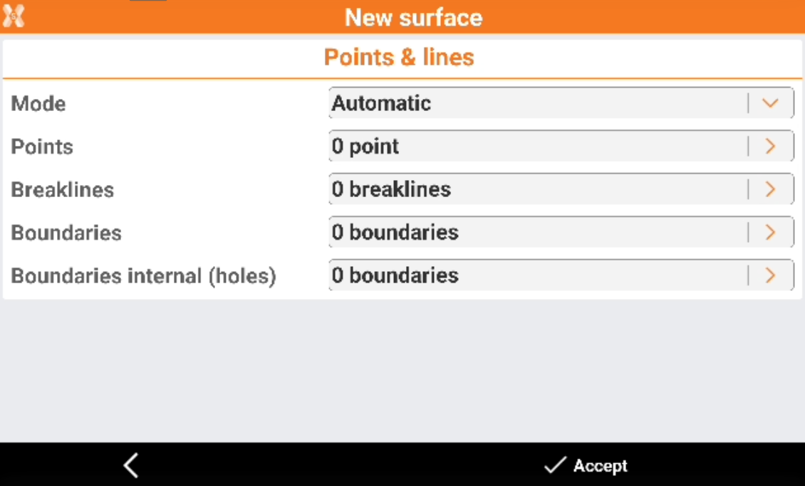
Mode: the triangulation mode can be manual or automatic.
Automatic: the surface is automatically triangulated using the defined points, breaklines and boundary lines.
Manual: activate this option to build the triangles composing the surface manually.
Points: define the set of points to use in case of automatic building. Press the button on the right of the input field to access the list of points or to a menu allowing to select points.
Load all points: all points from the archive are used to calculate the surface.
Select from table: select points from the points table. It is possible using this selection to use Selection rule function to select the points based on different rules, for example based on their code.
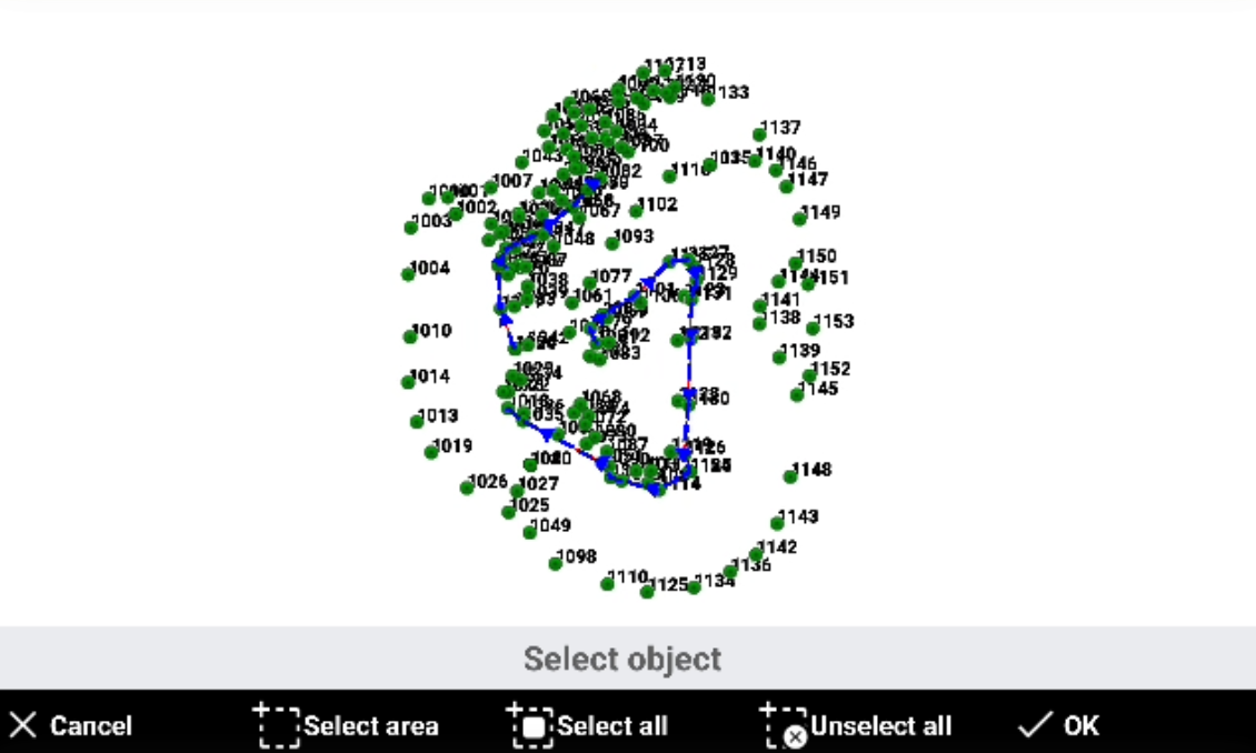
Select from CAD: select points from the graphic window.
Delete points list: delete the points loaded as vertexes of triangles.
Breaklines: specify the breaklines to check the shape of the surface. The breaklines must be inserted previously as polylines in the graphic window. Press the button on the right of the input field to access to a menu.
Select from CAD: select breaklines from the graphic window.
Clear all: delete the previously selected breaklines.
Boundaries: specify contour lines as border of the surface. The boundary lines must be inserted previously as polylines in the graphic window. Press the button on the right of the input field to access to a menu.
Select from CAD: select boundary lines from the graphic window.
Clear all: delete the previously selected boundary lines.
Boundaries internal (holes): specify contour lines as internal borders of the surface. These boundary lines will creates holes in the surface. The boundary lines must be inserted previously as polylines in the graphic window. Press the button on the right of the input field to access to a menu.
Select from CAD: select boundary lines from the graphic window.
Clear all: delete the previously selected boundary lines.
Press Accept to calculate the surface.
The software shows the calculated surface.
If instead the calculation mode was set to Manual, the triangles have to be manually created.