Ground to grid scale factor
 |
|  |
| 
Define parameters for the reduction of the distances measured with the total station to the sea level and at the cartographic plane.
Introduction to ground to grid scale factor
When mixing GNSS and TPS measurements, it is very important to be aware of the correct procedures to correctly mix the different measurements.
Imagine that you are measuring 2 points at approximately 500 meters with an RTK system and using the appropriate cartographic system (for example UTM). In this case the horizontal distance you should see in COGO or CAD is 500 meters. Then place the TPS on one of the 2 points and measure the other one: it is unlikely that the distance is the same, probably will be different. And, as consequence, the calculated point coordinate is different.
The TPS measures a slope distance that is then converted into horizontal distance using the vertical angle. But not only the vertical angle is used to calculate the horizontal distance, but also the geometric correction set by XPAD.
If the geometric correction is ignored, or set as 1, then ground distances are measured. If the correct geometric correction is applied, then grid distances are measured.
The picture can explain the difference between grid and ground distance.
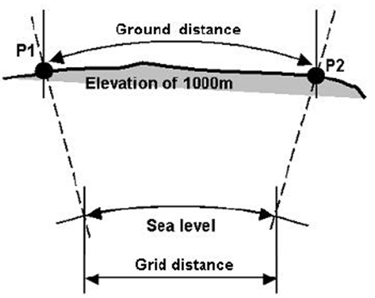
The geometric correction is critical because determines if the coordinates are ground coordinates or grid coordinates. Grid coordinates are created if grid distances are used; ground coordinates are created if ground distances are used.
Geometric corrections
There are 2 separate parts in the geometric correction calculation, the height scale factor and the cartographic plane scale factor.
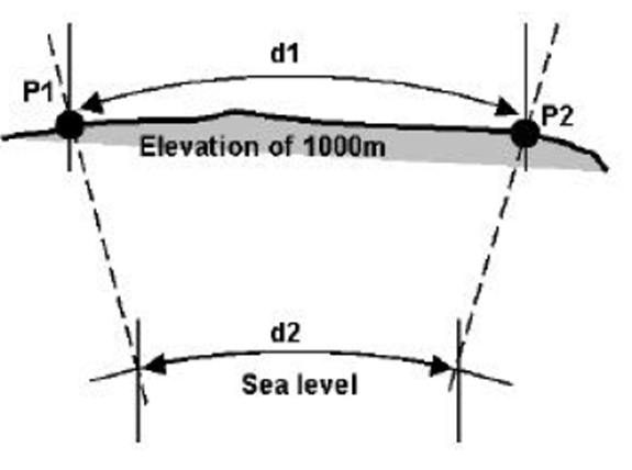
Imagine 2 points at sea level: measuring these 2 points we can measure 500 meters. Now imagine the 2 points at same location but at elevation of 1000 meters. In this case the distance will be bigger. The figure 2 can help to understand this difference.
The height scale factor allows the measured distance to be calculated at the sea level distance, that can be approximated as the ellipsoidal distance.
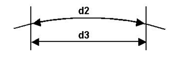
The cartographic plane scale factor allows instead to reduce the TPS measures to the cartographic grid.
If we measure 2 points with a GNSS system, the distance between these 2 points is a distance measured on a “flat” plane, described by the projection of the cartographic system. The same distance measured by the TPS will be probably different from the grid distance measured by the TPS.
To conclude there are 2 factors in the geometric correction. These 2 factors allow to reduce correctly a TPS distance (ground coordinates) to GNSS distance (grid coordinates).
The combined height scale factor and cartographic plane scale factor is simply called in XPAD as Combined Scale Factor.
Ground to grid scale factor in X-PAD
Click Job.
Click Coordinate system.
Click Ground to grid scale factor.
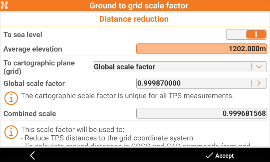
As described previously there are 2 components: the height scale factor and the cartographic plane scale factor. These 2 components define the Combined scale that is applied to TPS measurements to calculate the grid coordinates.
The height scale factor can be defined activating To sea level and entering the average elevation.
To sea level: activates to define the height scale factor: the reduction is calculated to the sea level based on the set average elevation.
Average elevation: allows to enter the average elevation to calculate the height scale factor.
The cartographic plane scale factor depends instead from the selected cartographic system. A cartographic system must be selected (see Cartographic system ).
None: the software does not apply a scale factor.
Global scale factor: the software uses a global scale factor valid for all measurements. If global scale factor is selected, then it is necessary to select a point from the database with a cartographic coordinate, so the scale factor can be estimated. A cartographic system must be set.
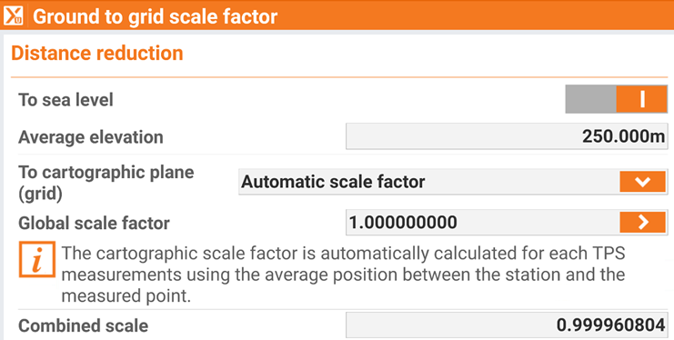
Automatic scale factor: the scale factor is calculated for each TPS measurement using the average position between the measured point and the total station. A cartographic system must be set.
As result X-PAD calculates a combined scale factor that is used to calculate TPS grid coordinates.
Ground to grid scale factor practical example
In this paragraph we will see the result of a total station free station orientation on GPS points when the scale factor is applied and when is not applied.
For this example, we measure 3 GNSS points, in a UTM cartographic system. Then using a total station, we perform a resection on the 3 GNSS points and visualize the residuals for the 3 points.
Since the distance between 2 points measured with GNSS (grid distance) is different from a distance measured with the TPS, we expect bigger residuals when a scale factor is not used.
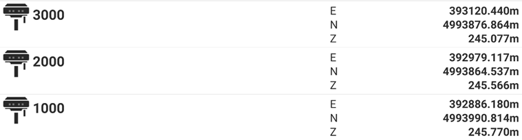
These are the 3 topographic points we use for the resection, measured in UTM cartographic system.
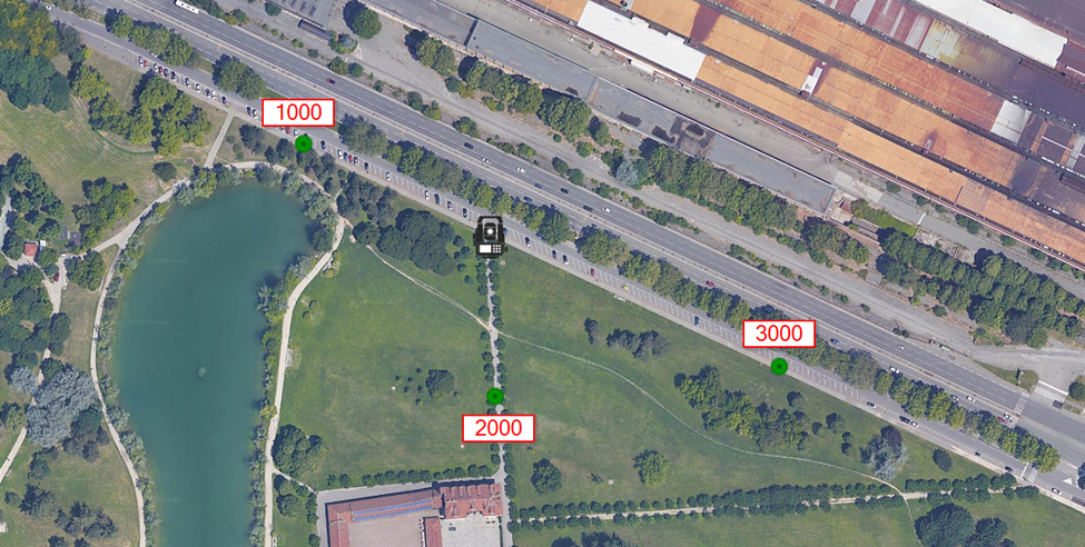
This is the location of the three points.
No ground to grid scale factor
For the first setup we do not use any ground to grid scale factor.
The residuals when no scale factor is used are:
Ref Point | Diff East | Diff North |
1000 | 0.027 | -0.016 |
2000 | 0.005 | 0.005 |
3000 | -0.034 | 0.002 |
Without a scale factor there are big residuals in particular on points 1000 and 3000.
Ground to grid scale factor
In the second test a ground to grid was selected
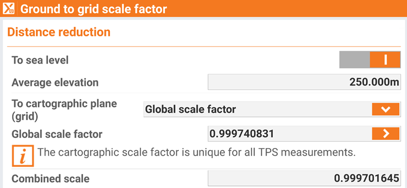
A global scale factor is used, estimating the scale factor based on point 2000
In this case the residuals are:
Ref Point | Diff East | Diff North |
1000 | 0.004 | 0.001 |
2000 | 0.002 | -0.005 |
3000 | -0.004 | 0.007 |
With a global scale factor the residuals have been reduced and are millimetric.
Automatic ground to grid scale factor
In the last example we use instead the automatic scale factor.
In this case the residuals are:
Ref Point | Diff East | Diff North |
1000 | -0.006 | 0.004 |
2000 | 0.003 | -0.002 |
3000 | 0.002 | -0.006 |
Again, the residuals are smaller than when no scale factor was used.