Local system – site calibration.
 |
|  |
| 
The system is created based on several points with known geographic and local plane coordinates.
From GNSS localization select Local - Site calibration.
Click Next or Details.
This opens a new page with the list of calibration points. Initially this list is empty.
In the table, pairs of points are listed which can be used for the calculation of the local system. For each pair, it can be defined if the data are used for the calculation of the plane transformation and for the elevation.
Based on the selection, the method for the calculation of the plane coordinates is selected automatically. For each pair, the deviations regarding the coordinates and elevations are calculated.
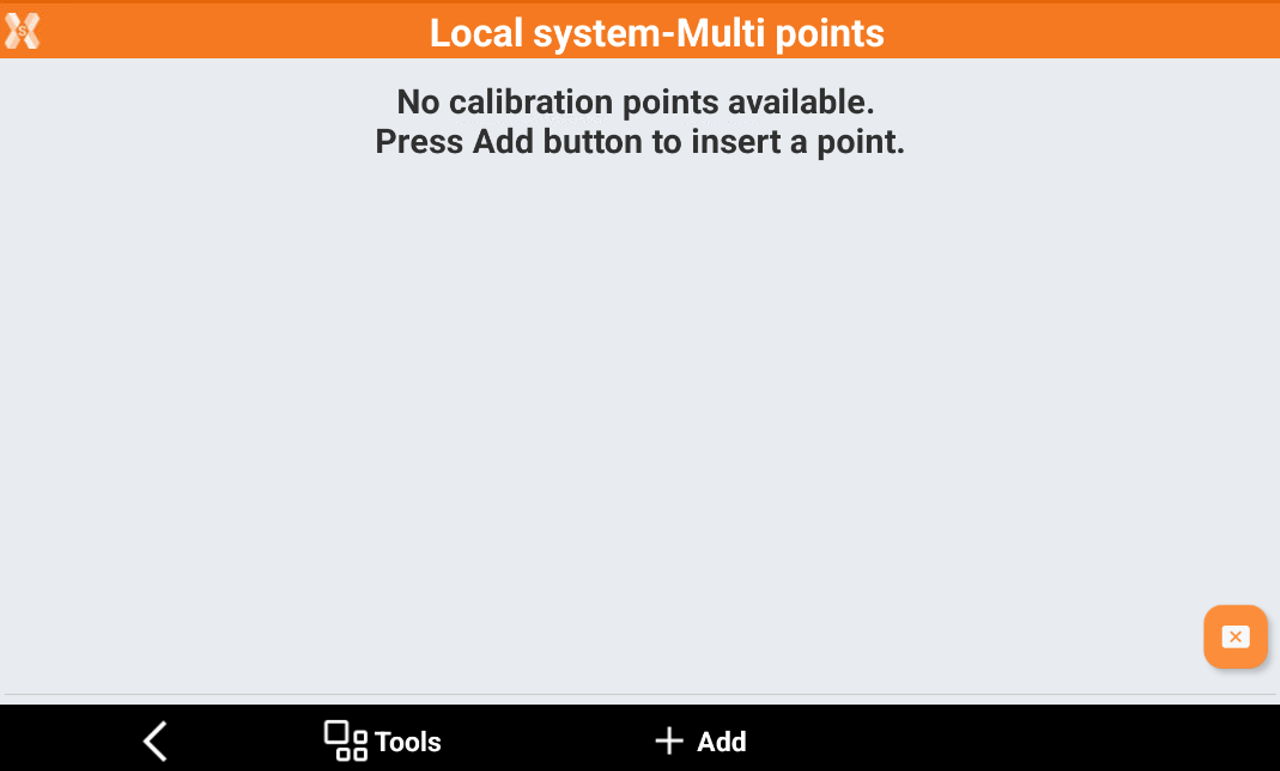
Click Add to add a new pair.
GNSS position
Specify the geographic coordinates of the GNSS point.
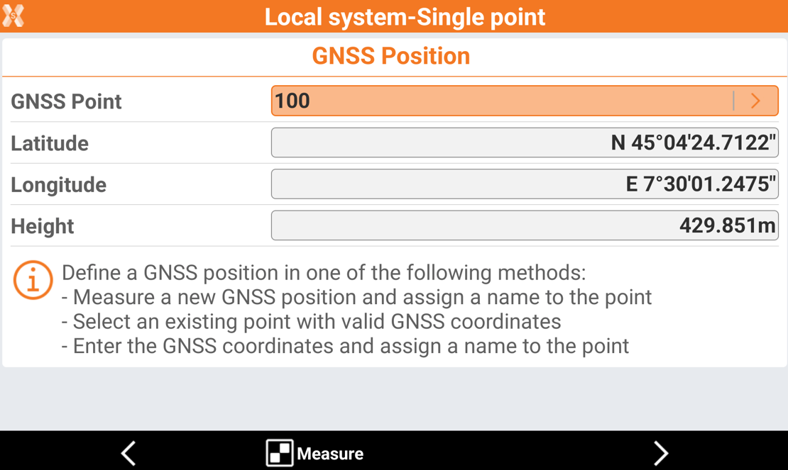
Click Measure to measure the GNSS point using the current GNSS profile
Or click on the arrow in GNSS Point to select an existing point.
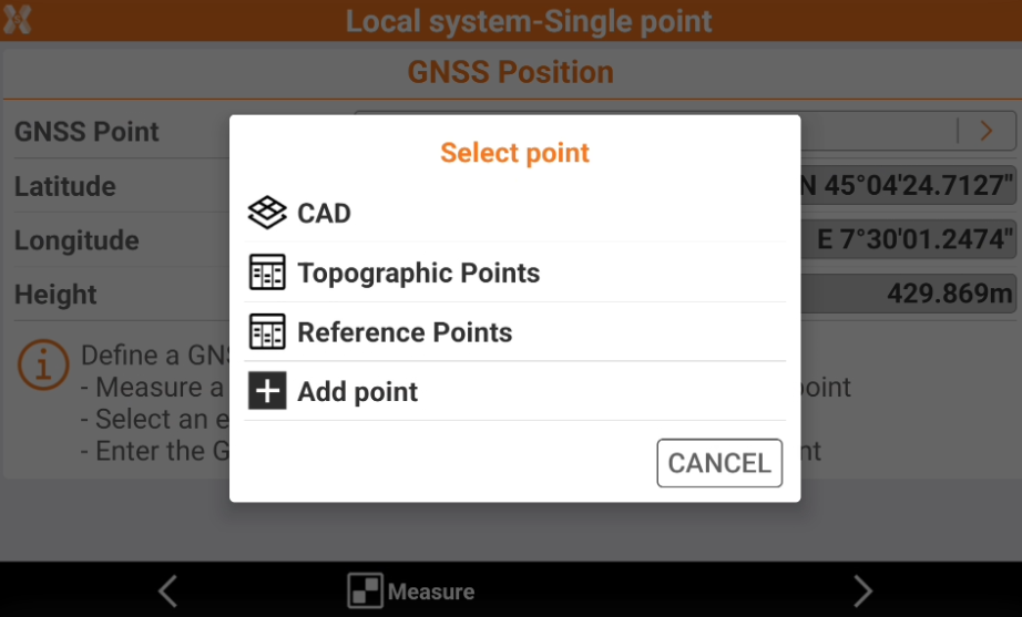
CAD: selects the point from CAD.
Topographic points: selects the point from the topographic points list.
Reference points: selects the point from the reference points list.
Add point: creates a new point entering the coordinates or from CAD.
Click Next to proceed in the following page, to define the local coordinate.
Local coordinate
This page allows to enter or select the local coordinate corresponding to the GNSS position previously entered.
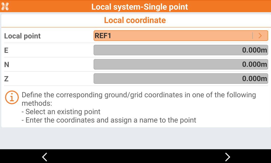
Click on the arrow in Local point to select an existing local point or create a new one entering the coordinates in the fields.
CAD: selects the point from CAD.
Topographic points: selects the point from the topographic points list.
Reference points: selects the point from the reference points list.
Add point: creates a new point entering the coordinates or from CAD.
Click Next to create the first pair.
Now using the same method continue to add more points.
Pairs of points table
After a pair has been added, it is possible to review the pairs of points table.
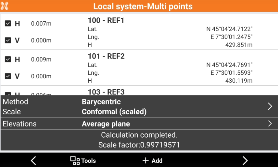
The software shows the deviations calculated for every point and the scale factor visualized in the lower part of the window.
Click H and V to disable the use of planimetric coordinate or vertical coordinate for the selected pair.
Select the mode of calculation to use for elevations.
Rigid body (unscaled): no scale factor is applied. The original distances between measured points are maintained.
Conformal (scaled): a scale factor is calculated and applied.
Helmert 3D: geometric transformation with 7-parameters within a three-dimensional space. A scale factor is calculated and applied.
Select the method for elevations:
Average plane: the software calculates the elevations using a sloped plane that minimizes the elevation differences.
Average shifts: the software calculates the elevations using the average shifts.
Click Next to proceed with the vertical system selection.
Specify the mode for the calculation to use for elevations.
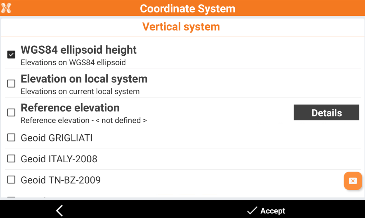
Click Accept to accept the system.
Tools of the GNSS localization page.
The Tools offers options for importing and compiling calibration points.
Import from reference points: allows to automatically import in the table points which have both the cartographic coordinates (North, East, elevation) and geographic coordinates (latitude, longitude, height).
Import FieldGenius RAW file: imports of calibration systems defined in a job created with software FieldGenius. The RAW file of FieldGenius is required.
Import Trimble DC/CAL file: imports the calibration system from Trimble in DC and CAL formats.
Import SurvCE LOC file: imports the calibration system from SurvCE program in LOC format.
Export for Topcon Machine Control: exports of the calibration system to Topcon Machine Control system.
Export SurvCE LOC file: exports of the calibration system for the SurvCE program in LOC format.
Delete all points: deletes all points of the calibration system.