Road stakeout
 + ROAD |
  + ROAD
The Road stakeout function allows to stakeout road axis selecting the reference axis, specify the chainage and the stakeout distance.
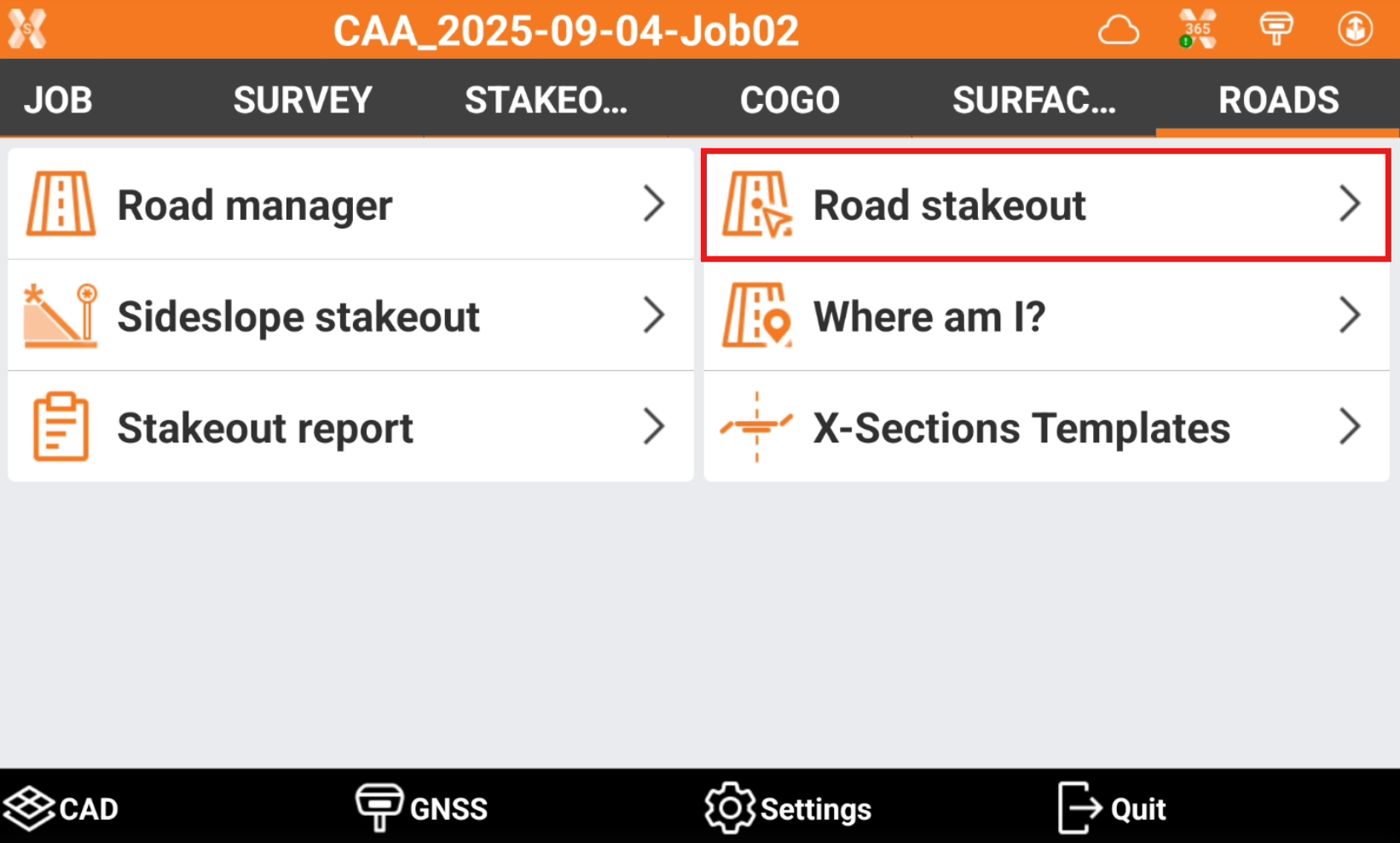
Click Roads.
Select Road stakeout.
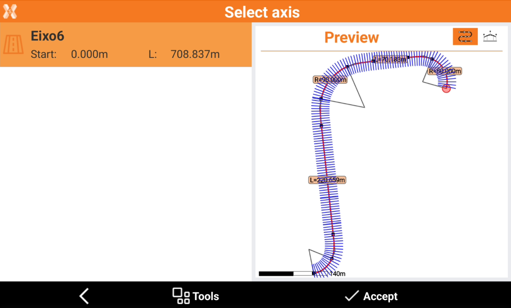
Select the road to stakeout and click Accept.
The software guides to select the station and offset to stakeout on the road design.
Station and interval
The next page allows to define the chainage for the road stakeout.
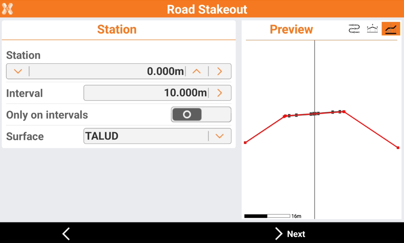
Station: the station to stakeout. Click
 and
and  to change the station of the defined Interval. Enter the station or click
  to define the station using different methods:
Measure: take a measure with the current instrument to calculate the station at the measured position.
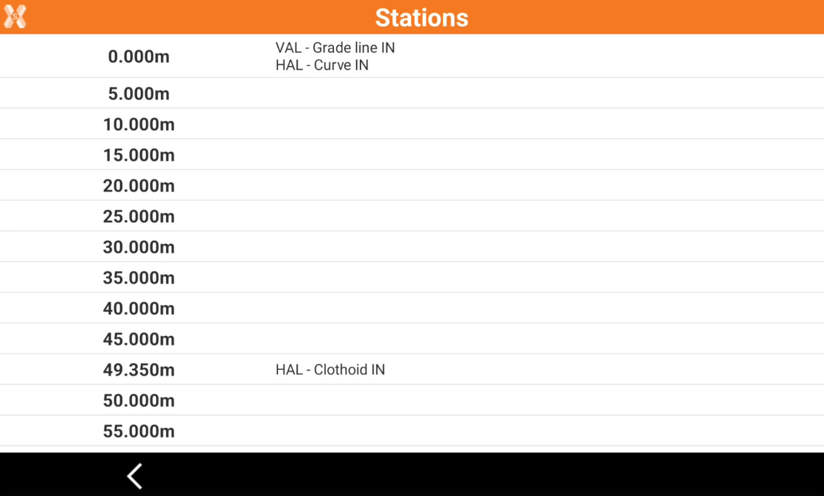
List: take the station from the list of available cross sections and change of road geometry (beginning of a curve, ending of a curve, etc.).
Topographic point: choose a topographic point from the list of points in Topographic point list.
Reference point: choose a reference point from the list of points in Reference point list.
CAD: choose the station directly from a point in CAD.
Interval: the interval to calculate the following stations. Click
to calculate the interval entering the number of segments the road has to be divided.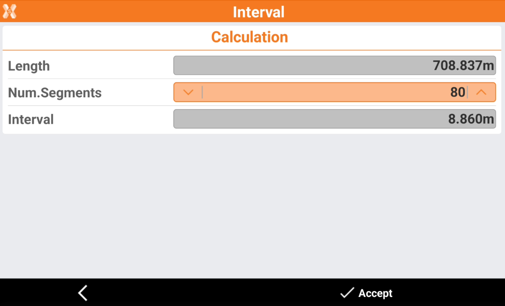
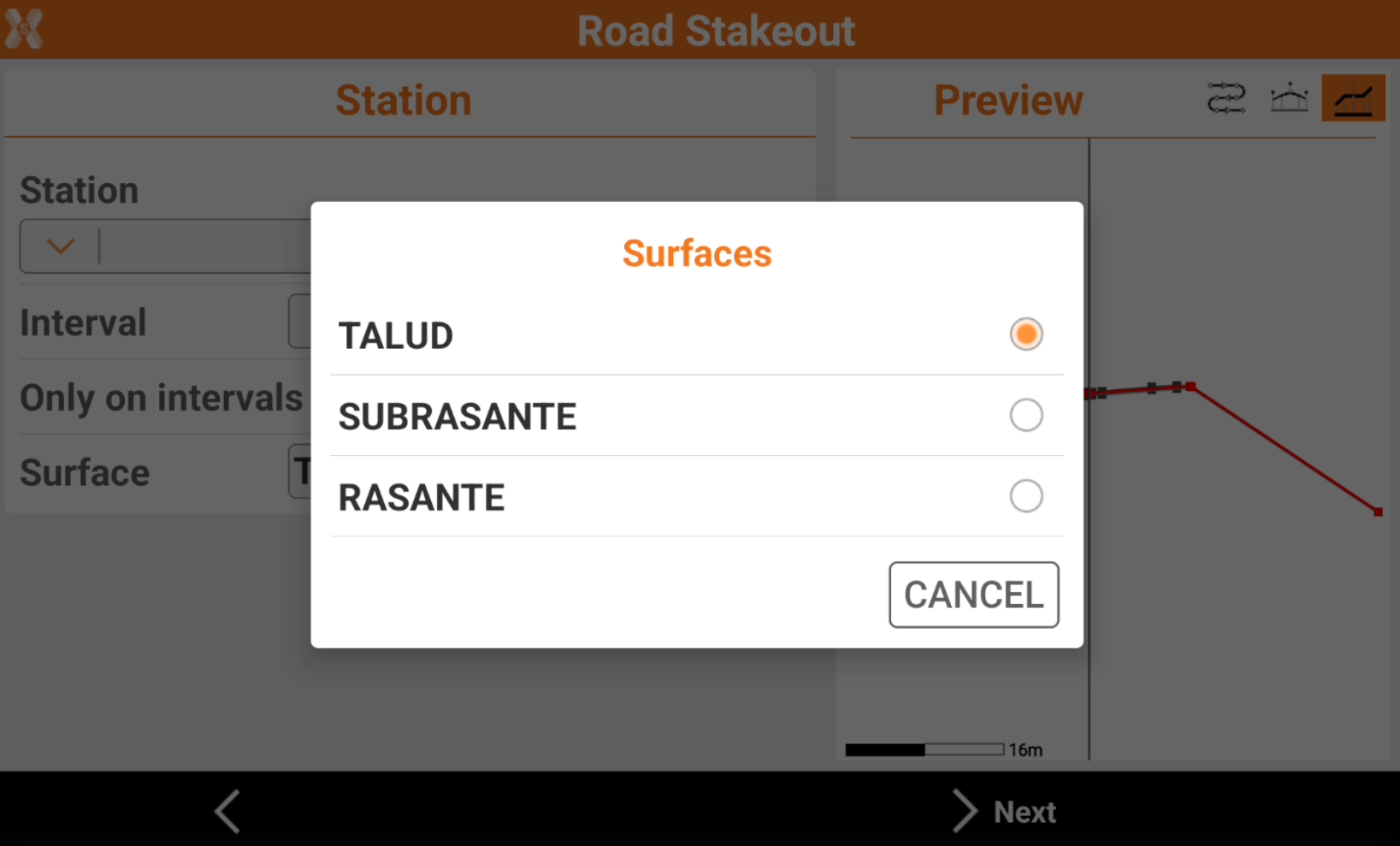
Only on intervals: if enables, stakeout the stations only at the specific value depending on Interval. If is disables, also stakeout the stations when the road geometry changes (beginning of a curve, ending of a curve, etc.).
Surface: if the road design has multiple layers, allows to choose the layer to stakeout.
On the right panel it is available a preview of the selected station.
 : to show the station position on the horizontal alignment.
 : to show the station position on the vertical alignment.
 : to show the cross section at the defined station.
Click Next.
Offset
The following page allows to select the vertex of the cross section to stakeout.
Click directly on the graphical preview to select a vertex to stakeout.
Click
and to change to previous or next vertex, in the Offset bar.Click
to select the vertex from the cross section view.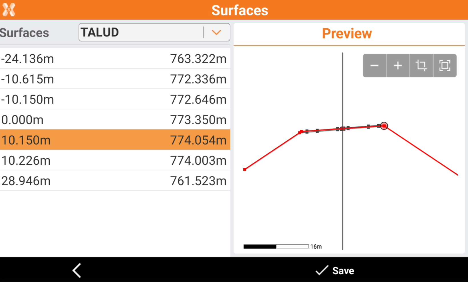
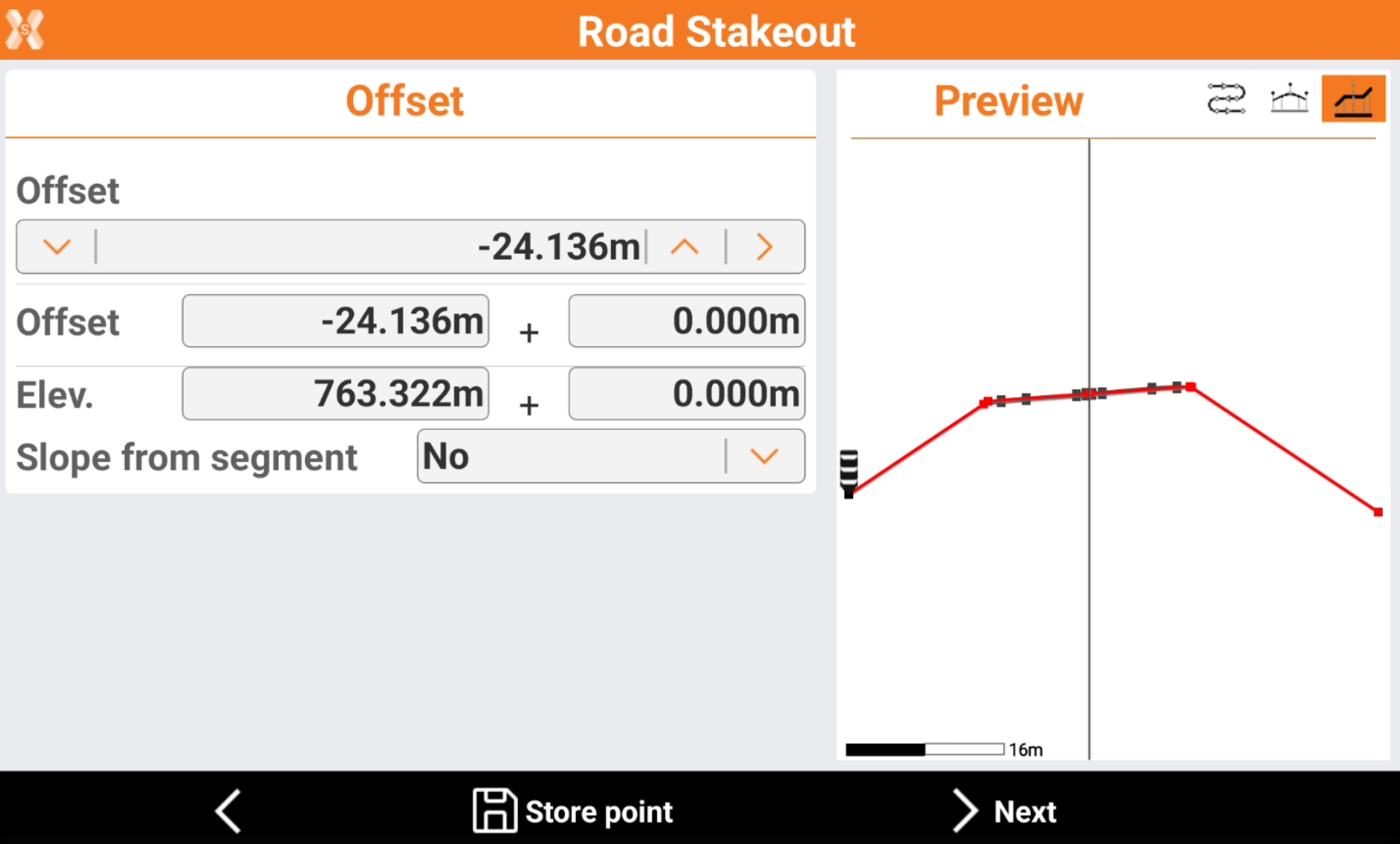
Or enter manually the values of offset and elevation.
Offset: the horizontal distance from the centerline. A negative value is on the left side of the cross section.
Elevation: the elevation of the point to stakeout.
Slope from segment: allows to apply the offset following the slope of the previous or next segment from the selected vertex. This option is useful when for example we want to extend an existing segment.
No: do not apply the offset using the slope from the previous or next segment.
Next segment: the offset is applied from the selected vertex using the existing slope of the segment after the vertex.
Previous segment: the offset is applied from the selected vertex using the existing slope of the segment before the vertex.
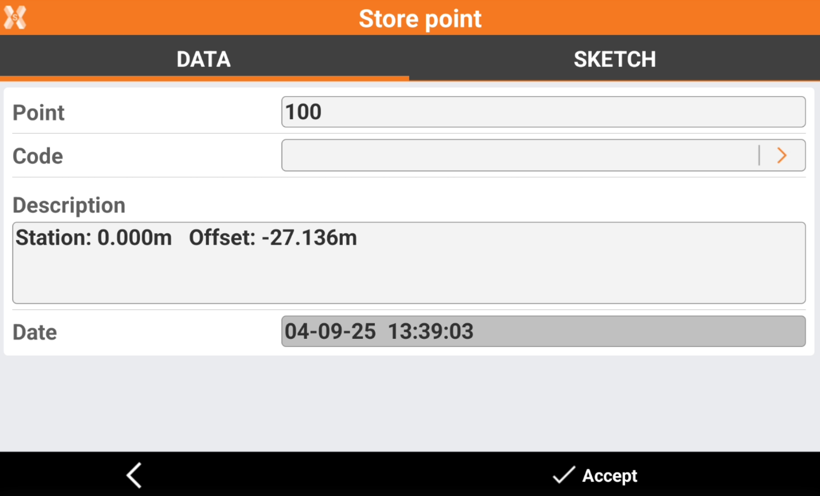
Click Store point to store the defined position in the Topographic point list.
Click Next to stakeout the point.
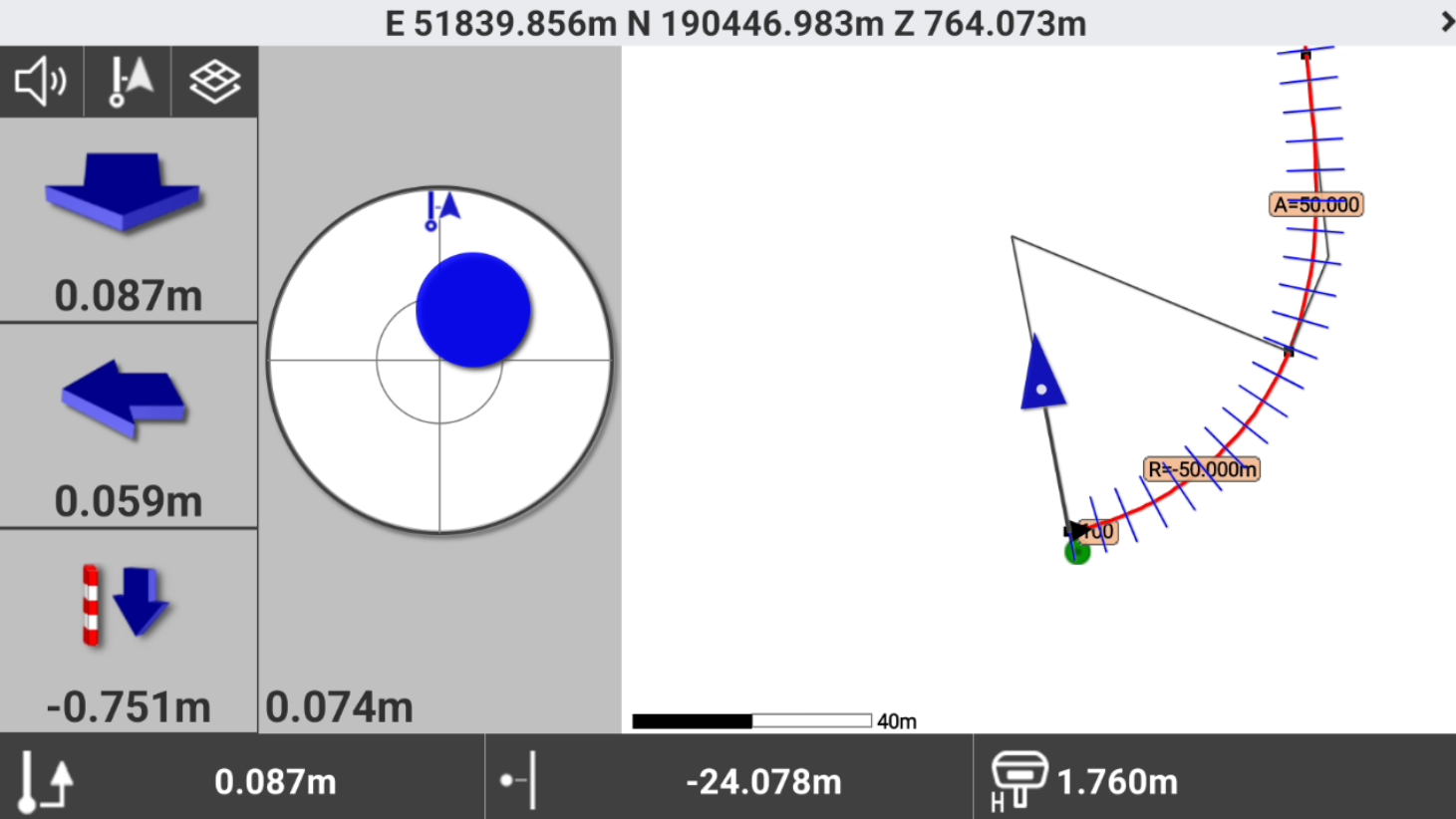
Stakeout the chainage and offset
Refer to Stakeout for more information on how to stakeout with GNSS and TPS.
The commands to stakeout are very similar to the standard point stakeout.
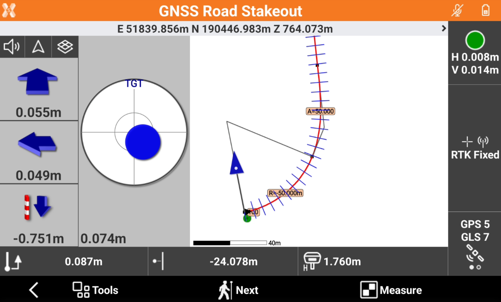
The left bar shows the indications to stakeout the point using the selected Reference for stakeout.
The bottom bar shows information on the position on the road design:
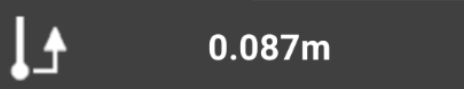 : current station.
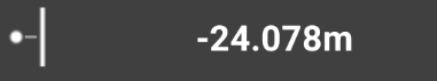 : current offset.
Click
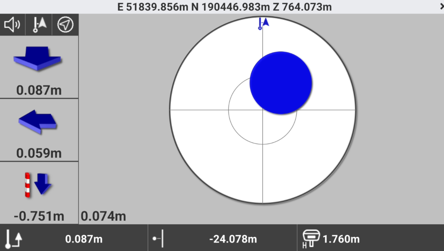
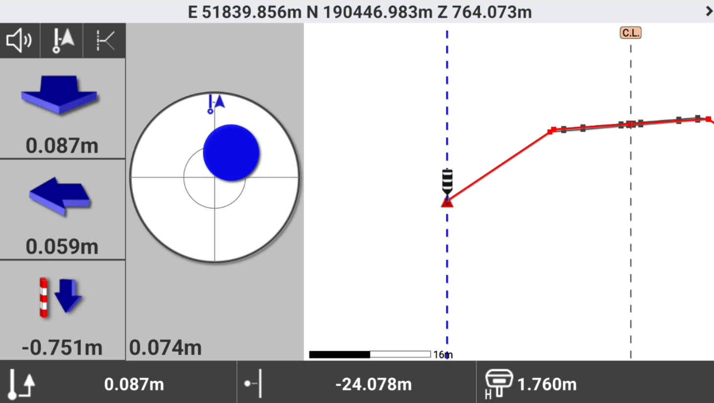
 to change the View mode.
CAD & Compass: shows the split screen with CAD view and compass view.
Compass: shows only the compass.
Cross section: shows the cross sections view.
Click Measure to save the stakeout measure.
Click Next to select the next point to stakeout.
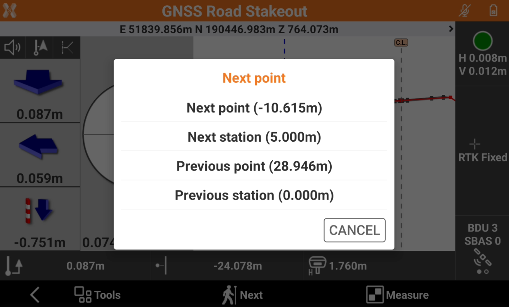
Next point: selects the next vertex on the cross section at the same station.
Next station: selects the next station and use the same vertex.
Previous point: selects the previous vertex on the cross section at the same station.
Previous station: selects the previous station and use the same vertex.