Sideslope stakeout
 + ROAD |
  + ROAD
The Sideslope stakeout function calculates the point of intersection of the project side slope with the existing terrain.
The position is calculated on the basis of a slope of project and referring to a chainage and to a distance (offset) on the reference axis.
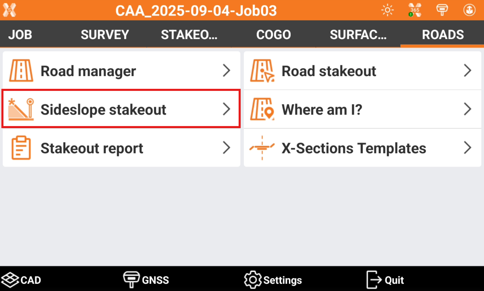
Click Roads.
Select Sideslope stakeout.
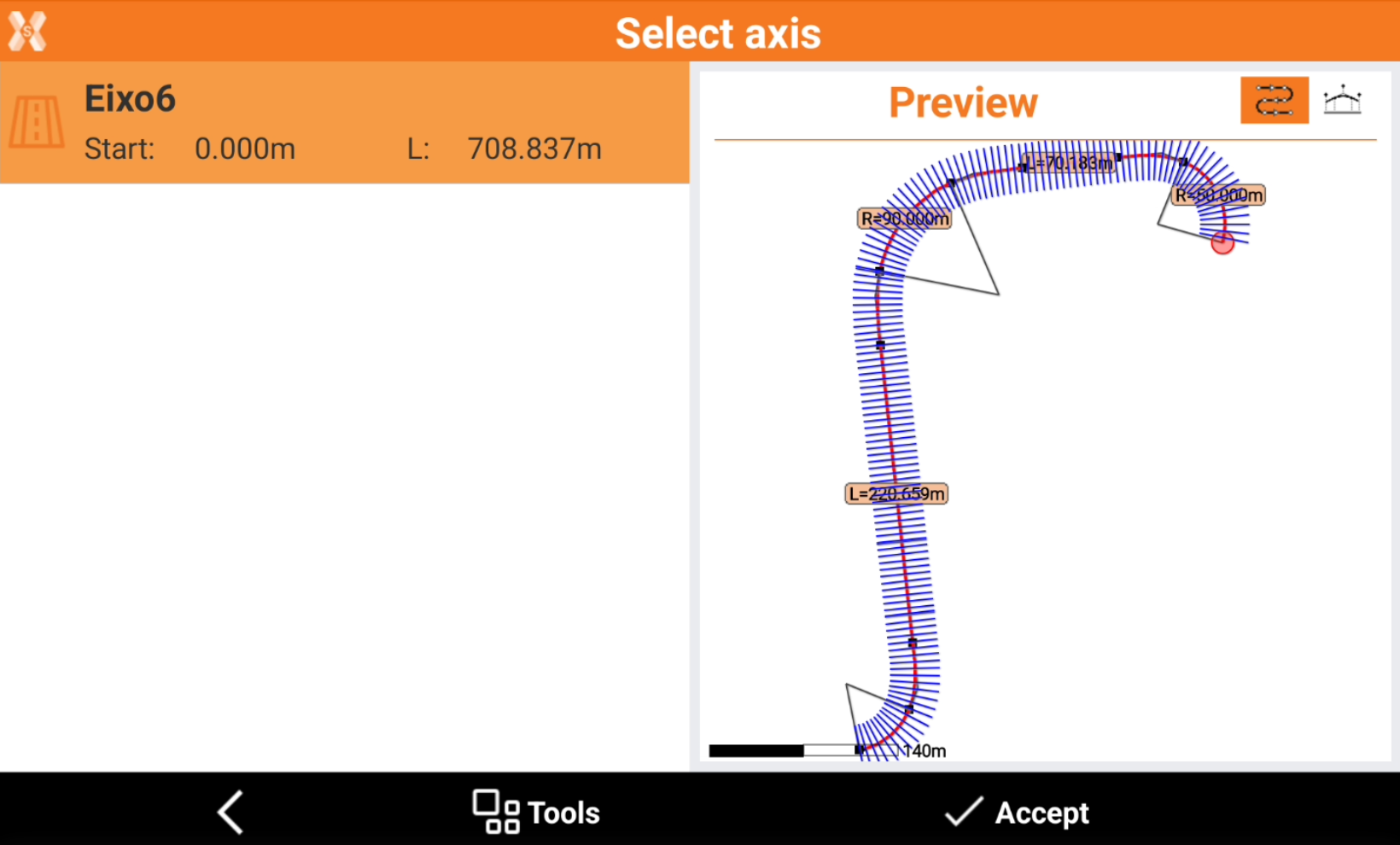
Select the road to stakeout and click Accept.
Station and interval
The next page allows to define the chainage for the road stakeout.
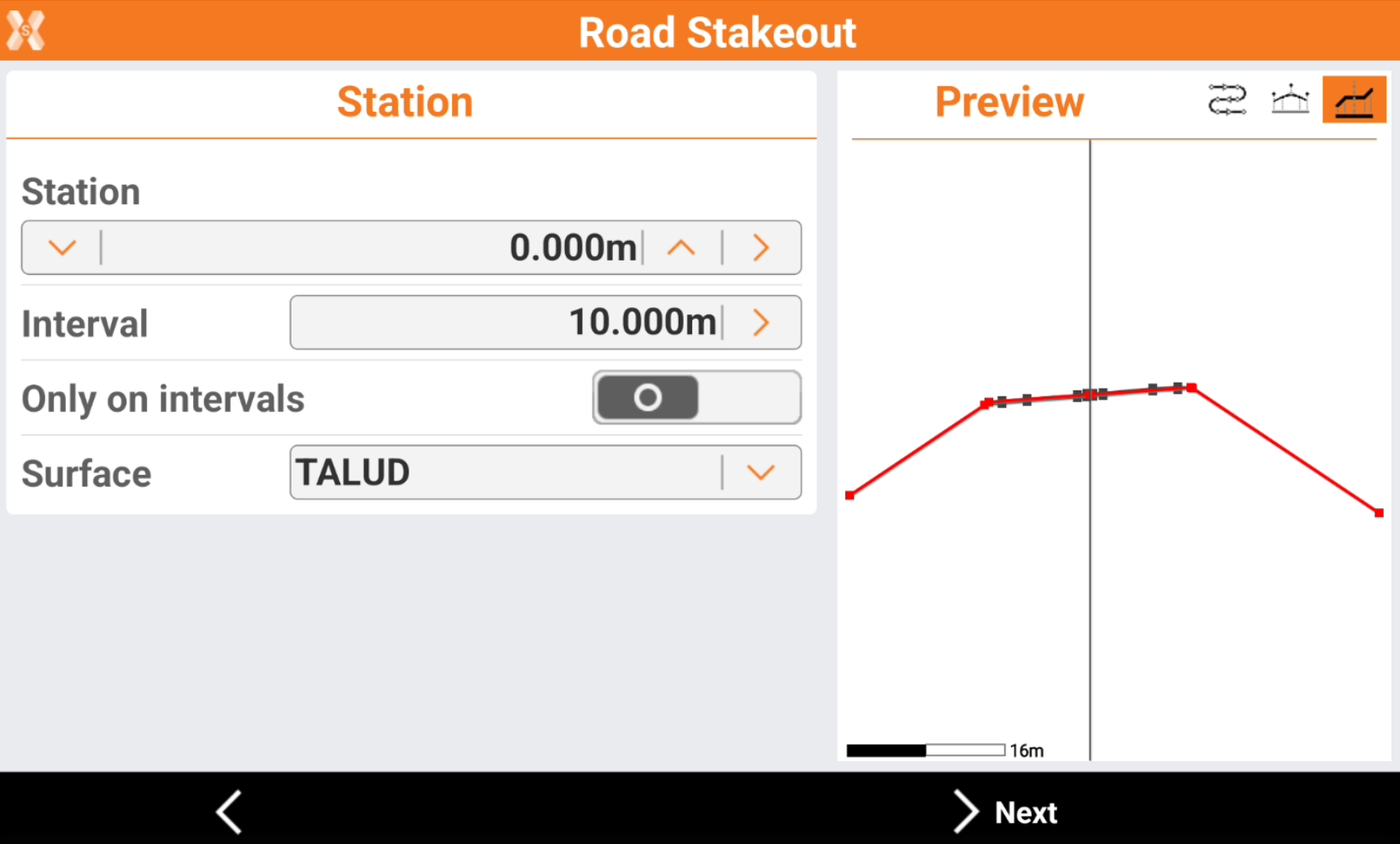
Station: the station to stakeout. Click
 and
and  to change the station of the defined Interval. Enter the station or click
  to define the station using different methods:
Measure: take a measure with the current instrument to calculate the station at the measured position.
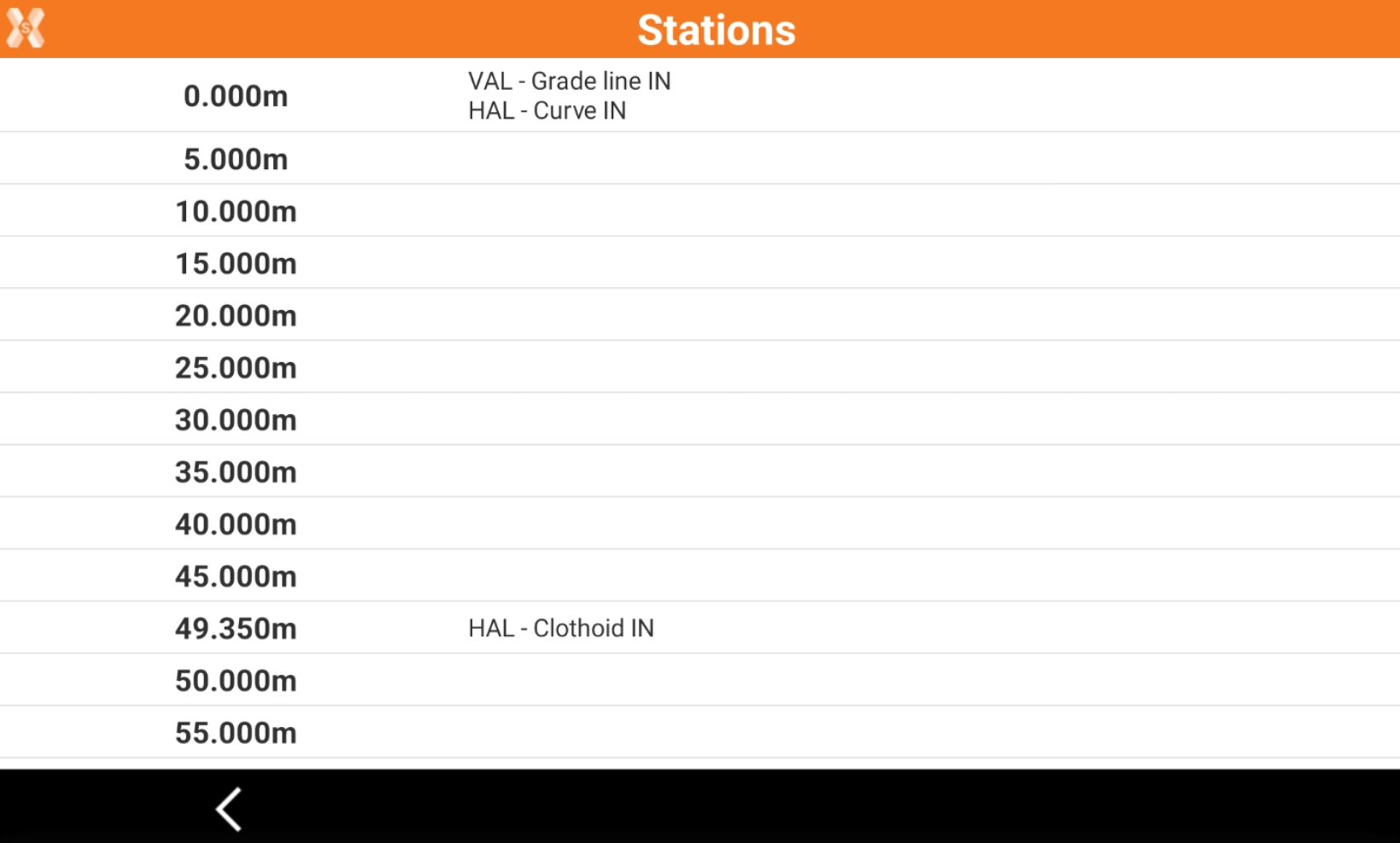
List: take the station from the list of available cross sections and change of road geometry (beginning of a curve, ending of a curve, etc.).
Topographic point: choose a topographic point from the list of points in Topographic point list.
Reference point: choose a reference point from the list of points in Reference point list.
CAD: choose the station directly from a point in CAD.
Interval: the interval to calculate the following stations. Click
to calculate the interval entering the number of segments the road has to be divided.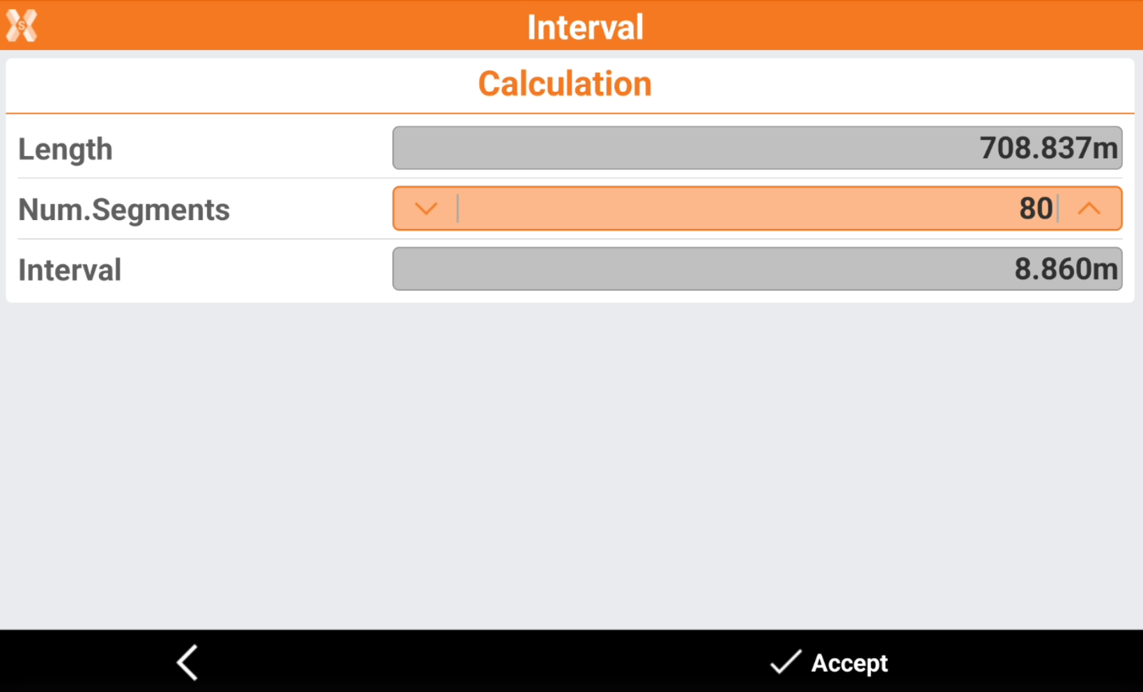
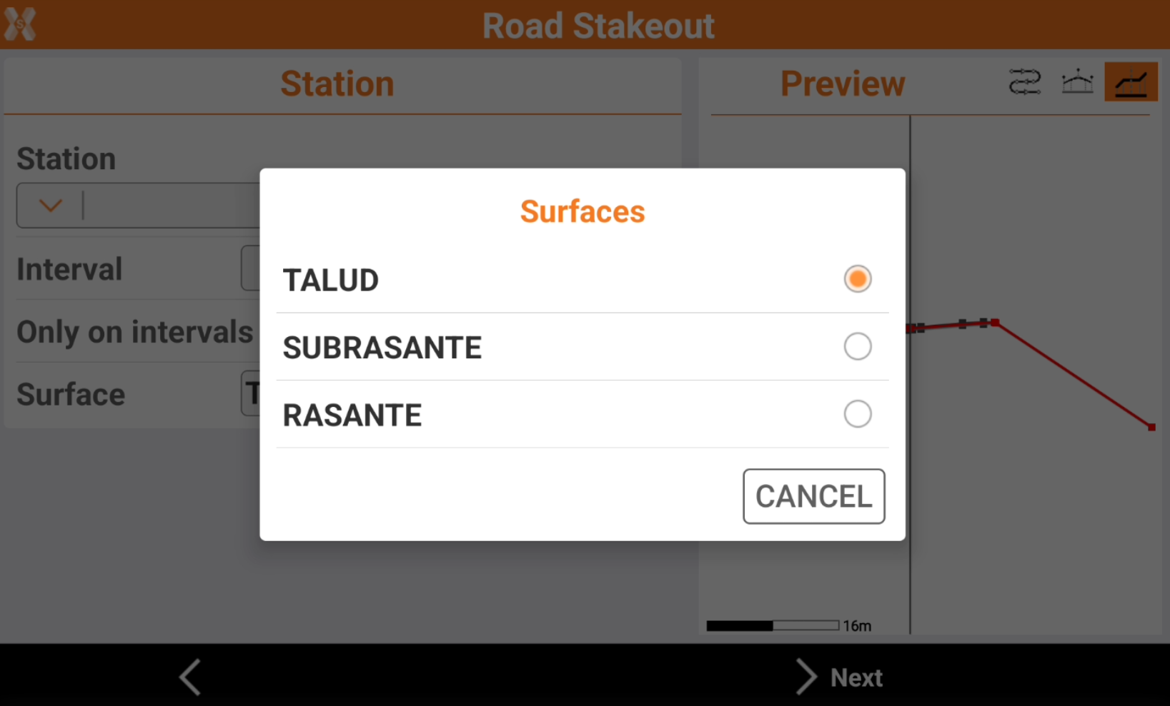
Only on intervals: if enables, stakeout the stations only at the specific value depending on Interval. If is disables, also stakeout the stations when the road geometry changes (beginning of a curve, ending of a curve, etc.).
Surface: if the road design has multiple layers, allows to choose the layer to stakeout.
On the right panel it is available a preview of the selected station.
 : to show the station position on the horizontal alignment.
 : to show the station position on the vertical alignment.
 : to show the cross section at the defined station.
Click Next.
Offset
The following page allows to select the vertex of the cross section from where the design slope is defined.
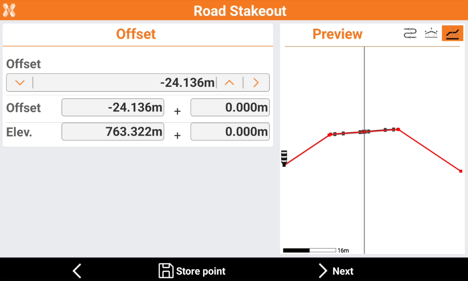
Click directly on the graphical preview to select a vertex.
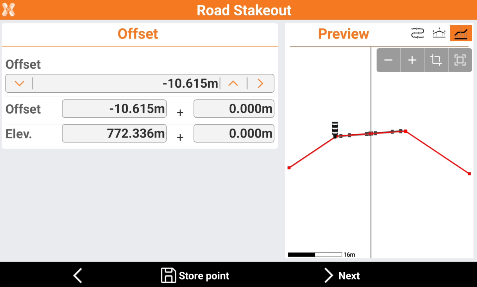
Click
and to change to previous or next vertex, in the Offset bar.Click
to select the vertex from the cross section view.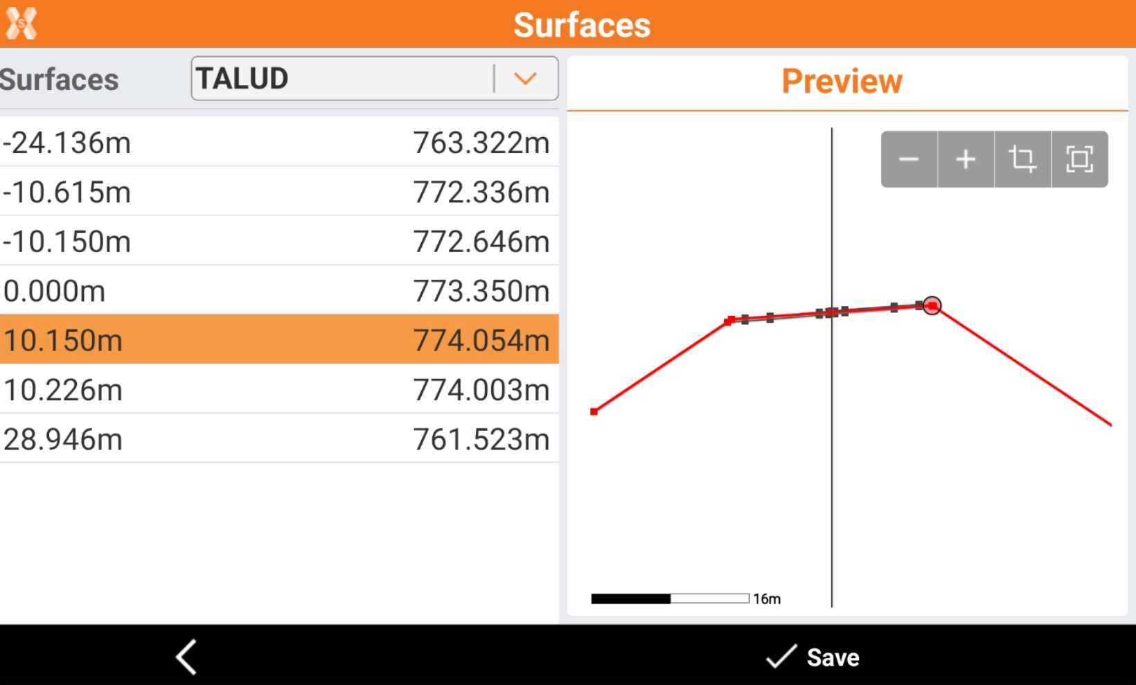
Or enter manually the values of offset and elevation.
Offset: the horizontal distance from the centerline. A negative value is on the left side of the cross section.
Elevation: the elevation of the vertex.
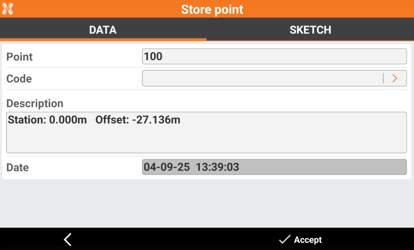
Click Store point to store the defined position in the Topographic point list.
Click Next to define the slope starting from the defined vertex.
Design slopes
The page requires to enter the design slope.
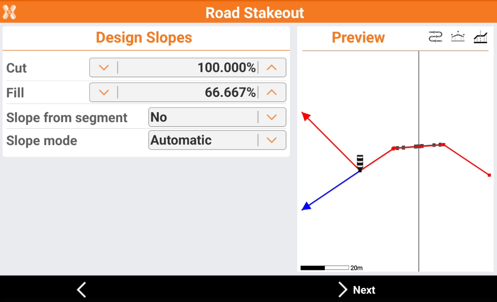
Cut: slope value in the cut condition. It is represented in the graphical preview with the red line.
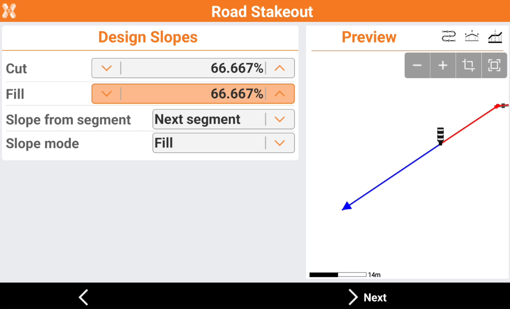
Fill: slope value in fill condition. It is represented in the graphical preview with the blue line.
Slope from segment: allows to calculate the slope according to the same slope value of the cross section segment before or after the selected vertex. This command is useful for example to extend the slope of a cross section segment.
No: the slope value is entered manually in Cut and Fill field.
Next segment: the slope value is the slope value of the cross section segment after the selected vertex.
Previous segment: the slope value is the slope value of the cross section segment before the selected vertex.
Slope mode: defines the cut or fill slope mode.
Automatic: If the receiver elevation is above the starting elevation of the side slope, the cut slope is used. If the receiver elevation is below the starting elevation of the side slope, the fill slope is used.
Cut: uses the cut slope.
Fill: uses the fill slope.
Press Next to stakeout the slope.
Stakeout the slope
Refer to Stakeout for more information on how to stakeout with GNSS and TPS.
The commands to stakeout are very similar to the standard point stakeout, but shows information specific to the slope stakeout.
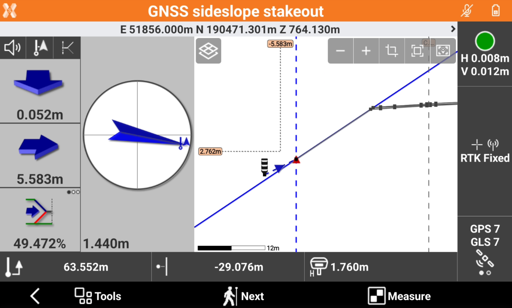
The left bar shows the indications to stakeout the reference vertex. The default reference for stakeout is Center line.
The bottom bar shows information on the position on the road design:
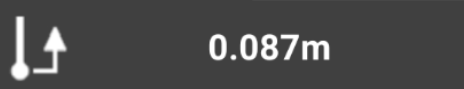 : current station.
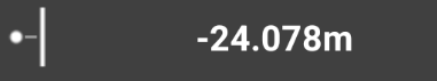 : current offset.
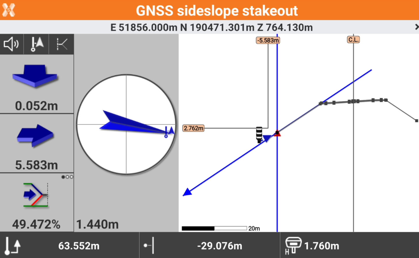
Click
 to change the View mode. The default view is Cross sections view.
CAD & Compass: shows the split screen with CAD view and compass view.
Compass: shows only the compass.
Cross section: shows the cross sections view, that is the most useful in the slope stakeout.
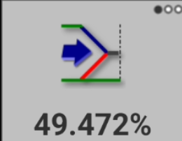
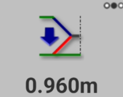
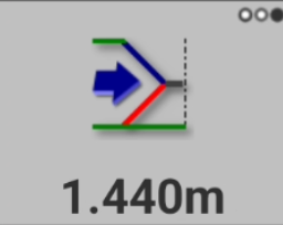
The bottom value in the left toolbar shows the stakeout information specific to the slope stakeout. Click to change information to display.
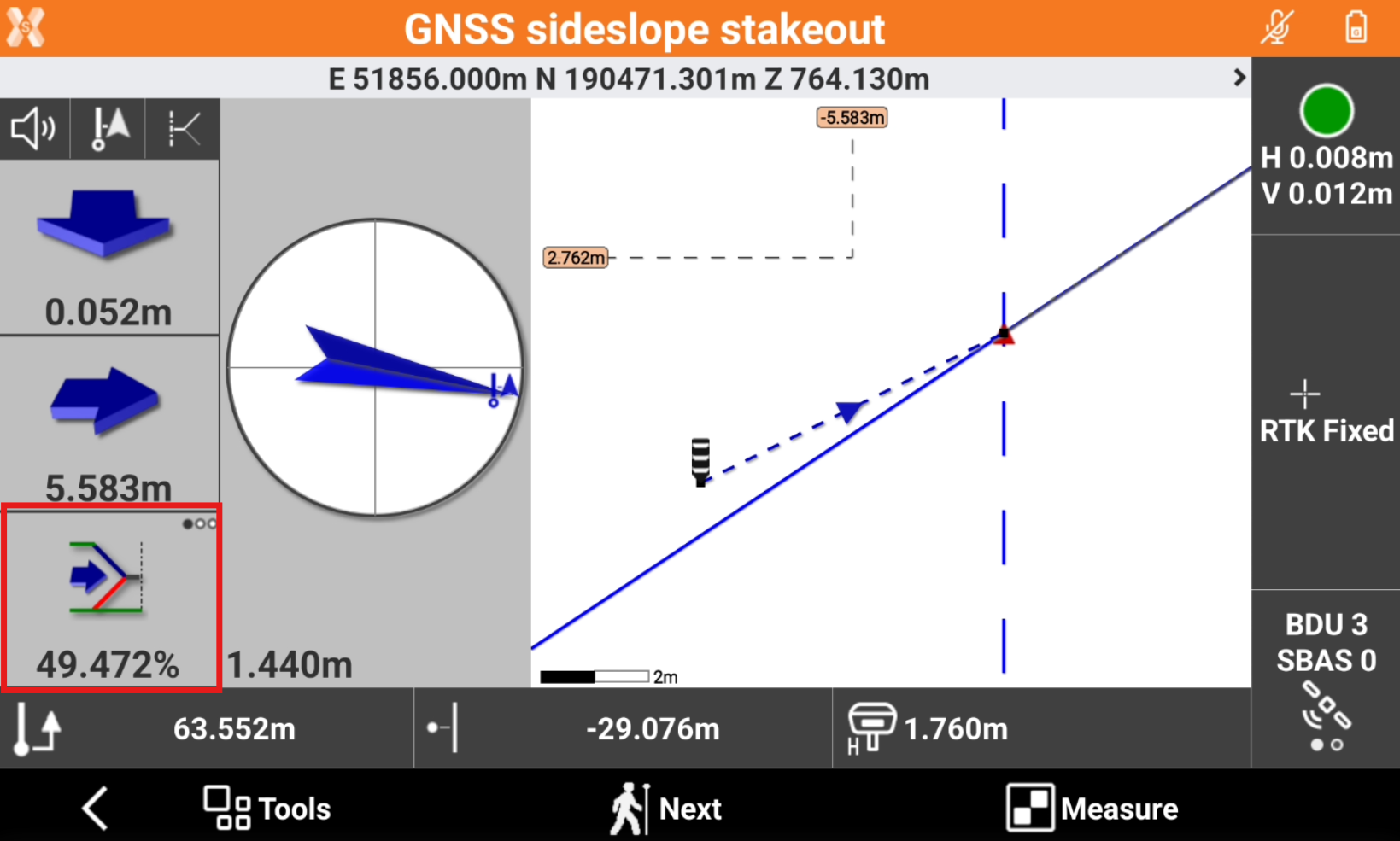
Current slope: shows the current slope from the reference vertex to the current position.
Vertical offset: shows the different elevation from the current position to the design slope.
Horizontal offset: shows the horizontal offset from the current position to the design slope.
Click Measure to save the stakeout measure.
Click Next to select the next station.
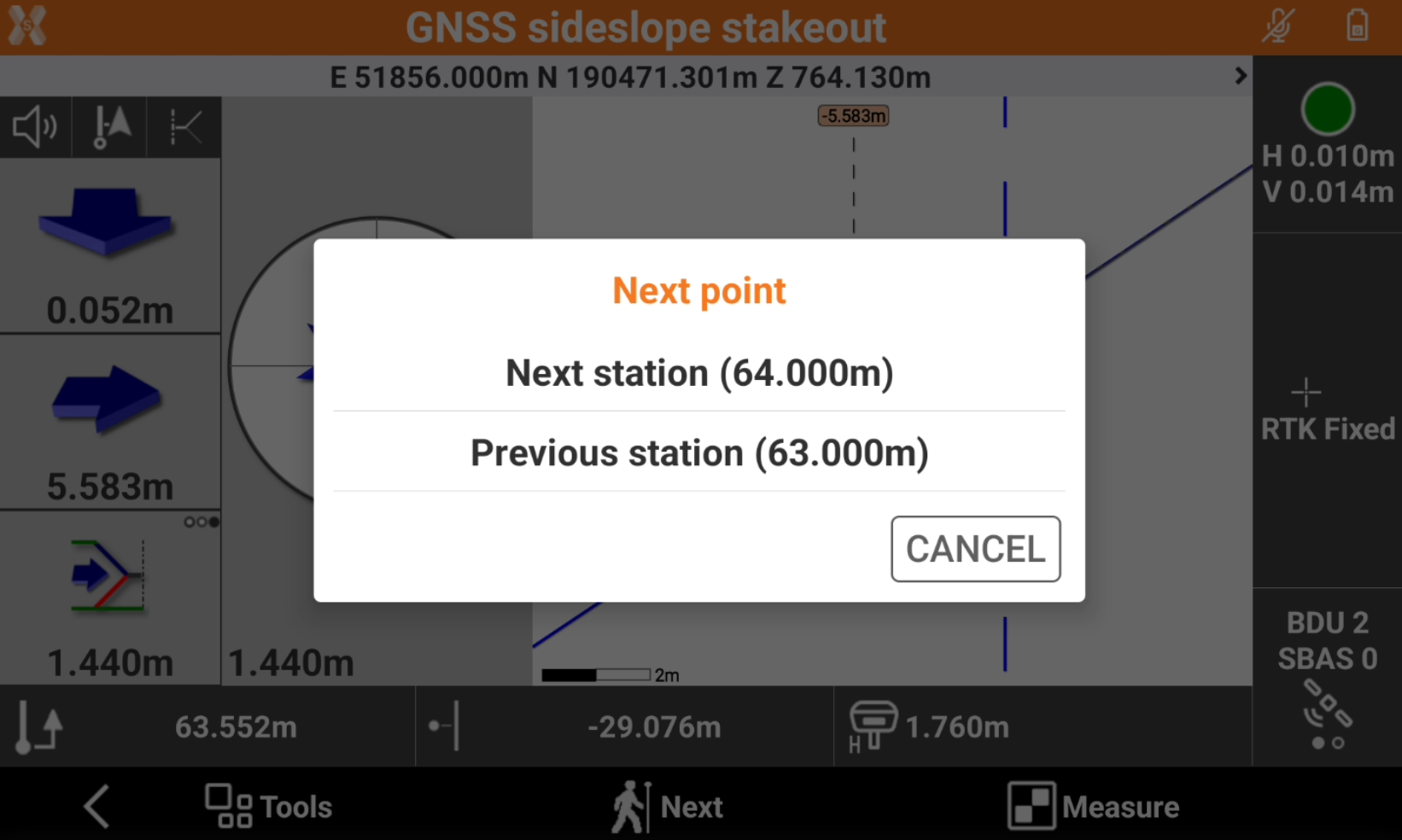
Next station: selects the next station according to selected interval.
Previous station: selects the previous station according to selected interval.