Stakeout chainage & offset
 |
|  |
| 
Stake out positions referring to a station distance and an offset distance on a reference element.
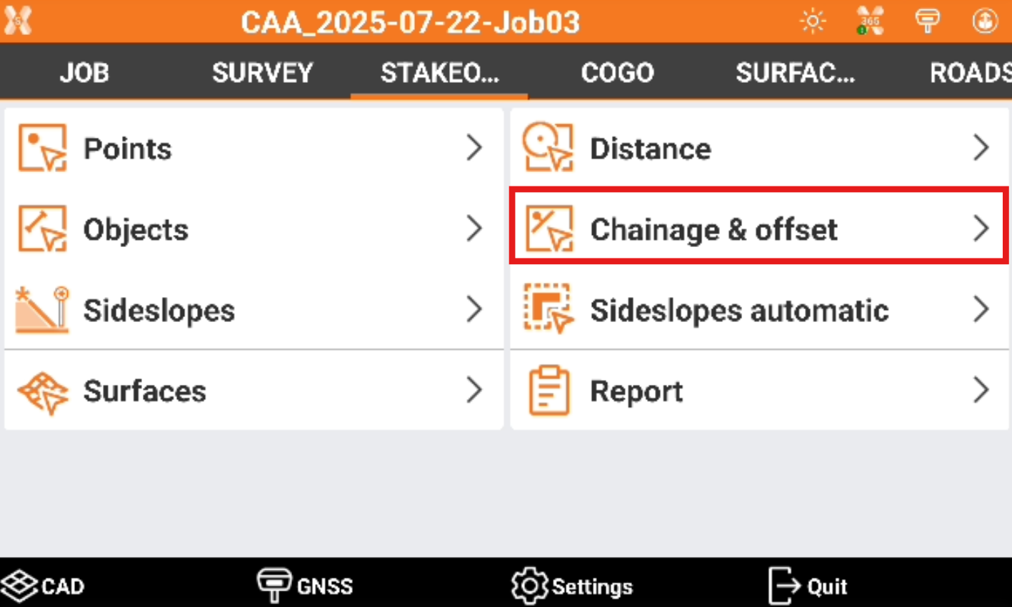
Click Stakeout.
Click Chainage & Offset.
Select the reference to stakeout.
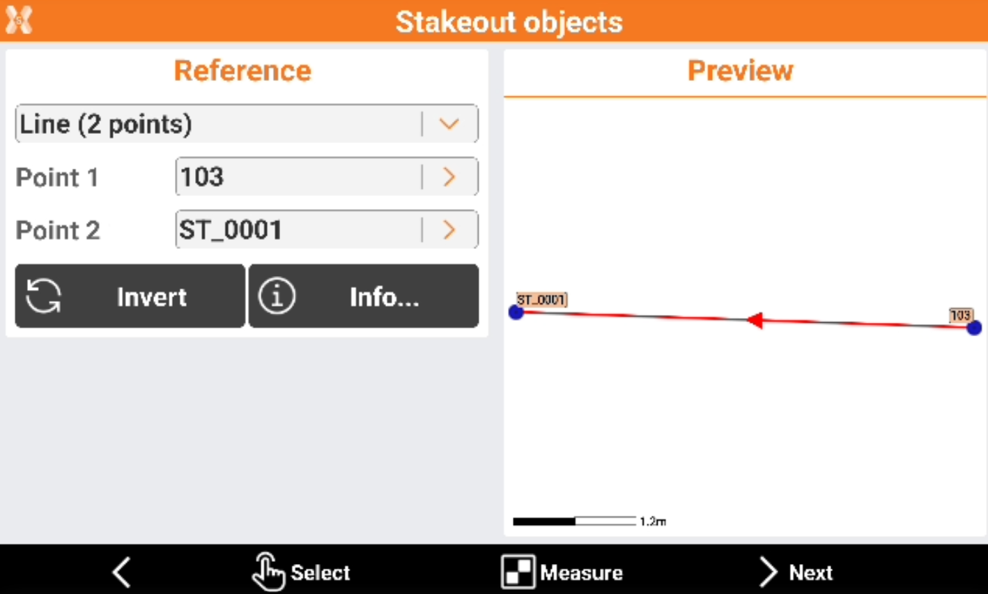
Reference to stakeout.
Line (2 points): line defined by two topographic points. Requires to select Point 1 and Point 2.
Arc (3 points): arc defined by three topographic points. Requires to select Point 1, Point 2 and Point 3.
Arc (2 points+R): arc defined by two topographic points and by the radius. Requires to select Point 1, Point 2 and arc radius.
Drawing object: select a line, polyline, arc or circle in the graphic window. This option allows for example to stakeout a drawing element imported.
Click Invert to invert the reference direction.
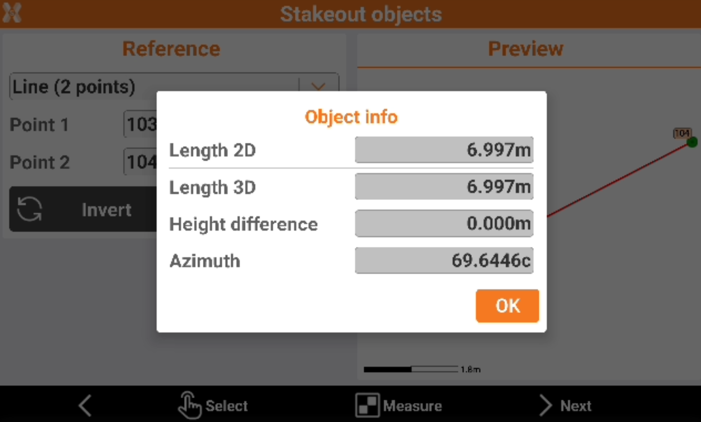
Click Info to have information on the reference object.
Click Select to pick the points directly from CAD or click Measure to measure the reference points.
After the reference object has been selected click Next to define the parameters.
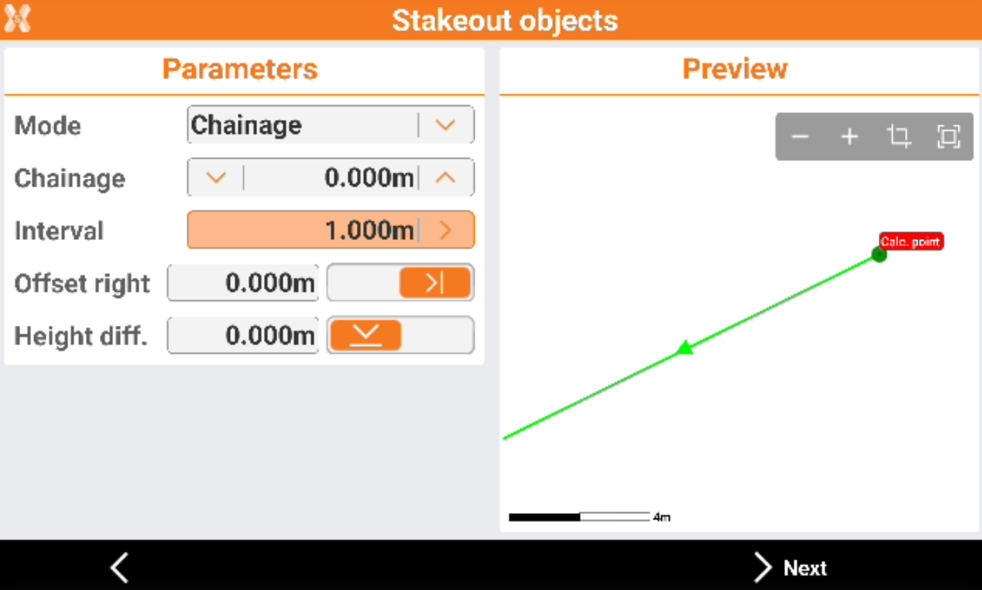
Mode: select the stakeout mode.
Chainage: stakeout the object at defined chainage.
Vertices: stakeout the vertices of the object.
Chainage and vertices: stakeout the object at defined chainage and at all vertices.
Chainage: distance on the reference element on which is the position to reach.
Interval: distance between the stakeout points along the reference element. Use the button on the right to calculate the interval dividing the length of the reference element in a defined number of parts. Selectable if method is chainage or chainage and vertices.
Offset: distance perpendicular to the reference element. Use the button on the right to define if the desired position is on the right or on the left of the reference element.
Height diff.: elevation difference to apply to the calculated point. The software interpolates the elevation on the reference element with the defined station distance. A slope can be added to the interpolated elevation.
After having defined the reference element and the offset parameters, the main stakeout window appears.
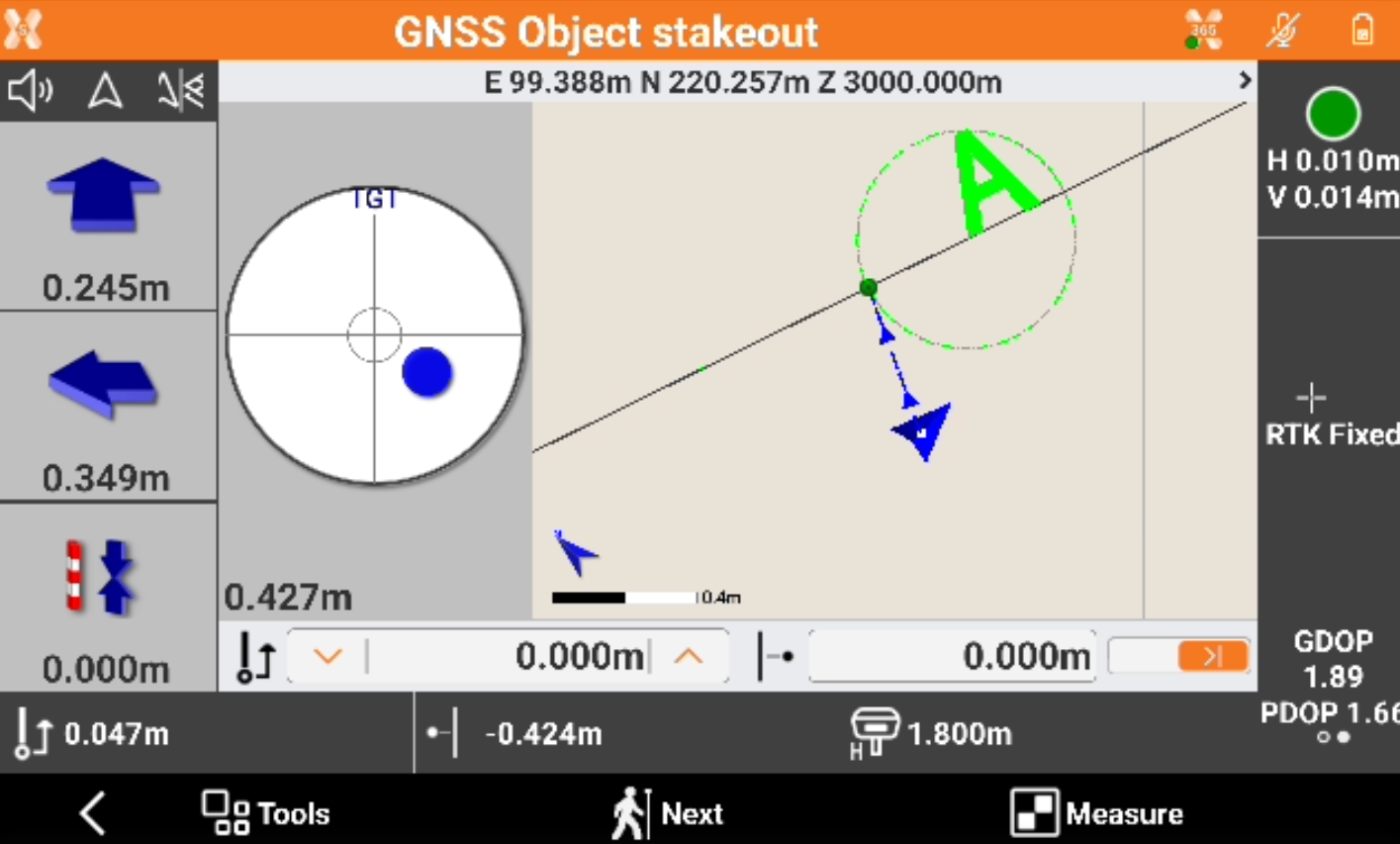
The distance from the station and the offset of the position are displayed at the bottom.
When staking with offset, change the distance and the offset directly in the stakeout window.
Information of stakeout:
 : visualizes the distance from the end of the object.
 : visualizes the distance from the beginning of the object.
Refer to Stakeout - GNSS and Stakeout - TPS for the commands in this page.
Tap Measure to start measuring the stakeout point. The acquisition of positions for the number of epochs set in survey parameters starts. The epochs are acquired if the conditions defined for accuracy check are met. Otherwise the software keeps waiting for a manual stop or until the conditions are met.
When the number of defined epochs is reached, confirm the Stakeout results are displayed.
Click Accept to store the point.