Stakeout sideslopes automatic
 + BUILD |
The function allows to stakeout sideslopes that start from a closed polyline and that represent, for example, the bottom of an excavation.
The funciton is used to:
Finding the catch point with the existing ground.
Checking side slopes created by the excavator.
Click Stakeout.
Click Sideslopes automatic.
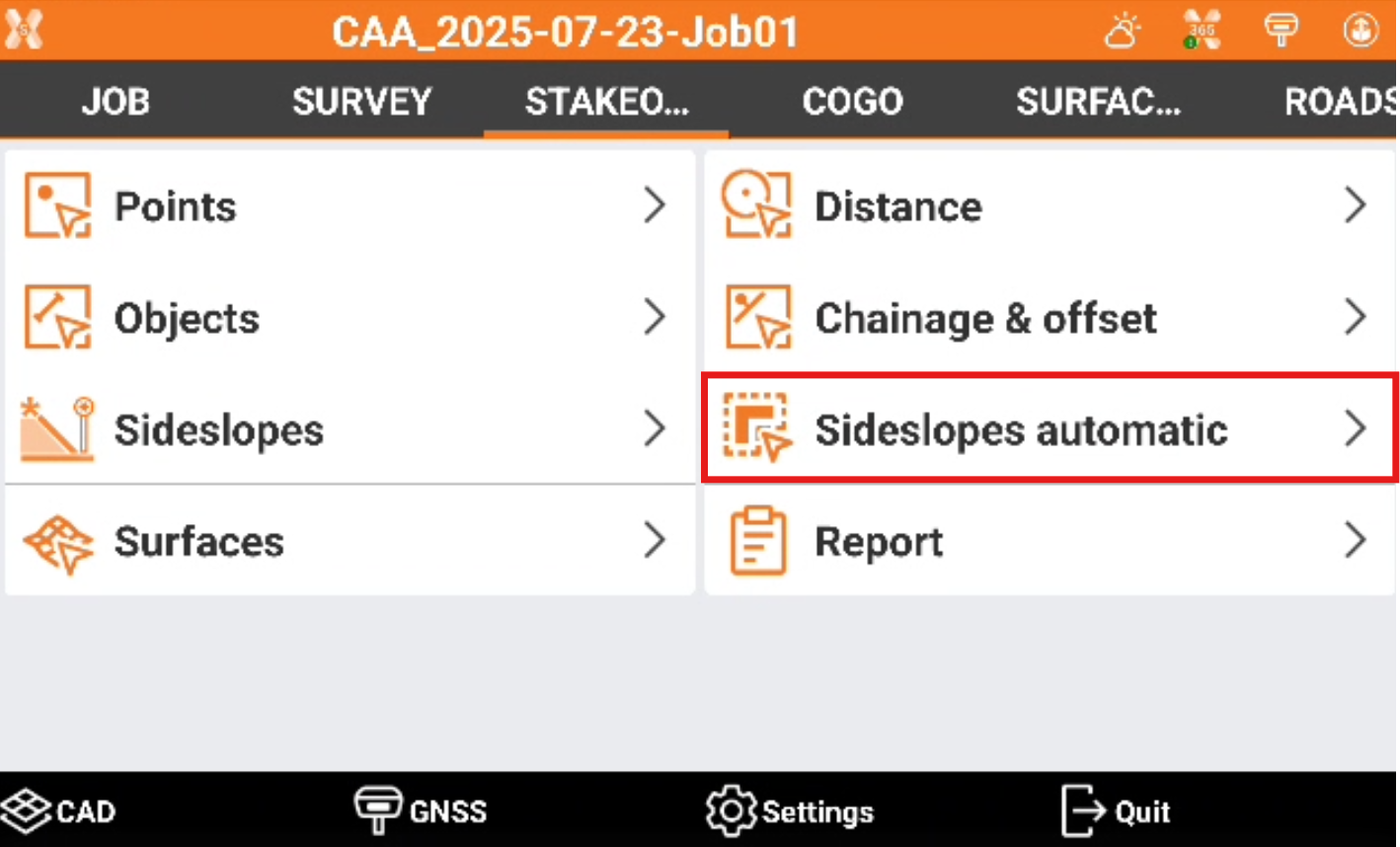
The Automatic sideslopes page is opened.
Automatic sideslopes settings
The page allows to enter the sideslope parameters and have a graphical preview of the result.
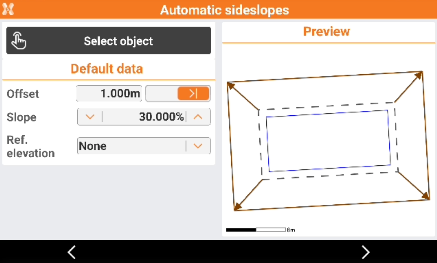
Click Select object to select the polyline from CAD, that represents the bottom of the excavation.
Define:
Offset: horizontal distance from the selected polyline to the side slope.
Slope: slope between the polyline and the current position.
Ref. elevation: sets the reference elevation to use for the elevation check.
None: the reference elevation is not used. The software uses the elevation as defined in CAD.
Foundation elevation: allows to enter the elevation of the foundation.
Reference elevation and excavation height: allows to enter the reference elevation of the terrain and the height of the excavation. The foundation elevation is automatically calculated.
Click Next.
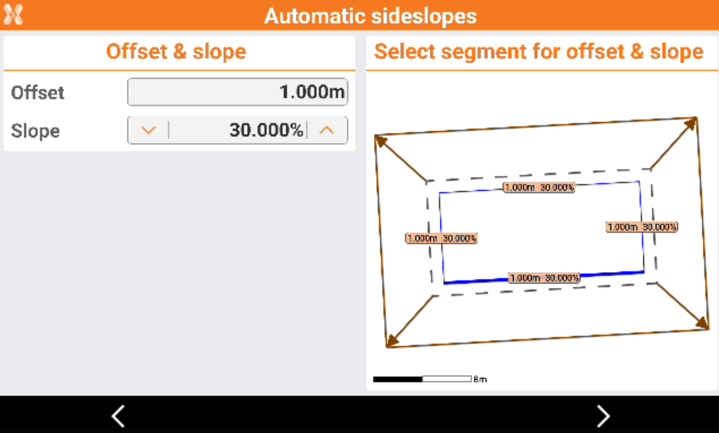
For each segment is possible to customize the offset and the slope. Click a segment to define its slope and offset.
Sideslope stakeout
Click Next.
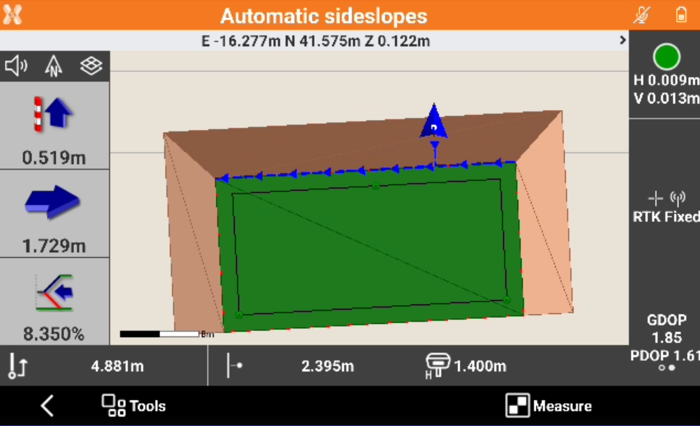
The position along the side slope is calculated and displayed.
First value refers to the current elevation below or above the reference elevation defined by the slope. Second value refers to the horizontal distance from the position to side slope. Third value shows the current value of the slope and the direction to take, on the perpendicular to the reference element, to achieve the project slope value.
Click
 to change to cross section view.
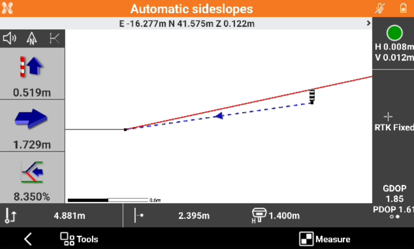
This view shows in a cross section view the current position and the current slope (blue line) together with the design slope (red line).
Click Measure to measure the position.
Create measured surface
The software can generate the surface of the sideslope using the measured data.
Click Tools and select Create surface.
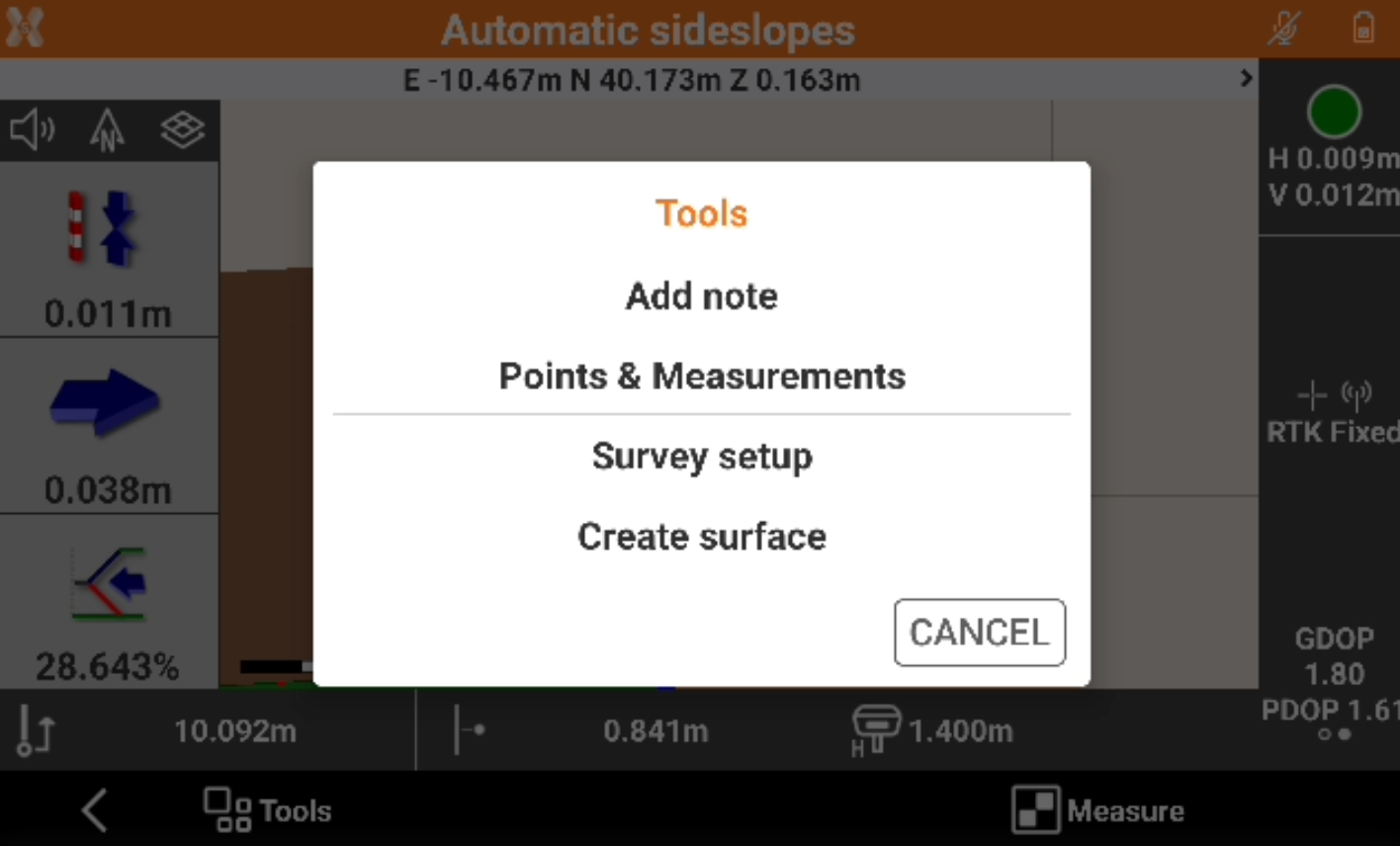
The software generates a surface using the measured points on the sideslope.