Where am I?
 + ROAD |
  + ROAD
The function Where am I? provides information about the current position in relation to the selected road project (road design) or a a 3D surface.
The function allows to stakeout the road design data without the need to specify a station and an offset.
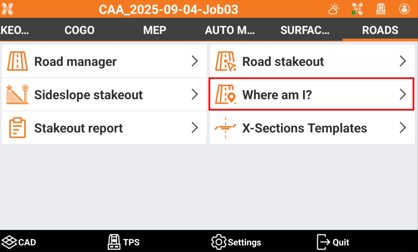
Click Roads.
Click Where am I?.
Select the road to stakeout.
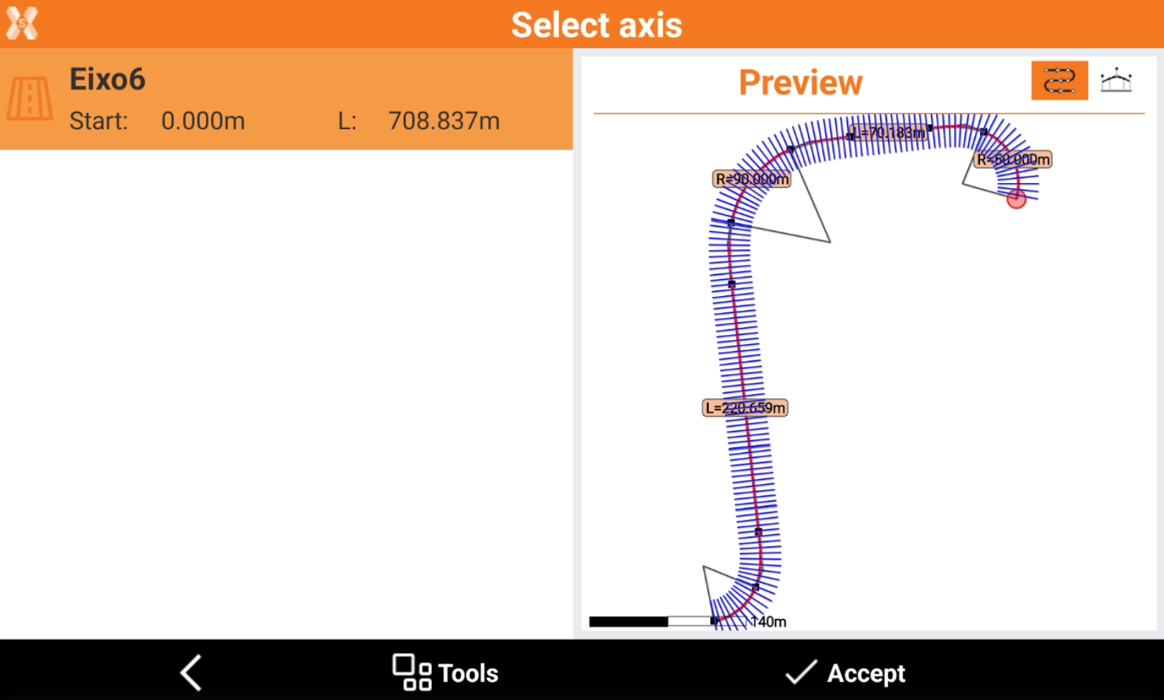
The software shows the current target position in relation to the road design.
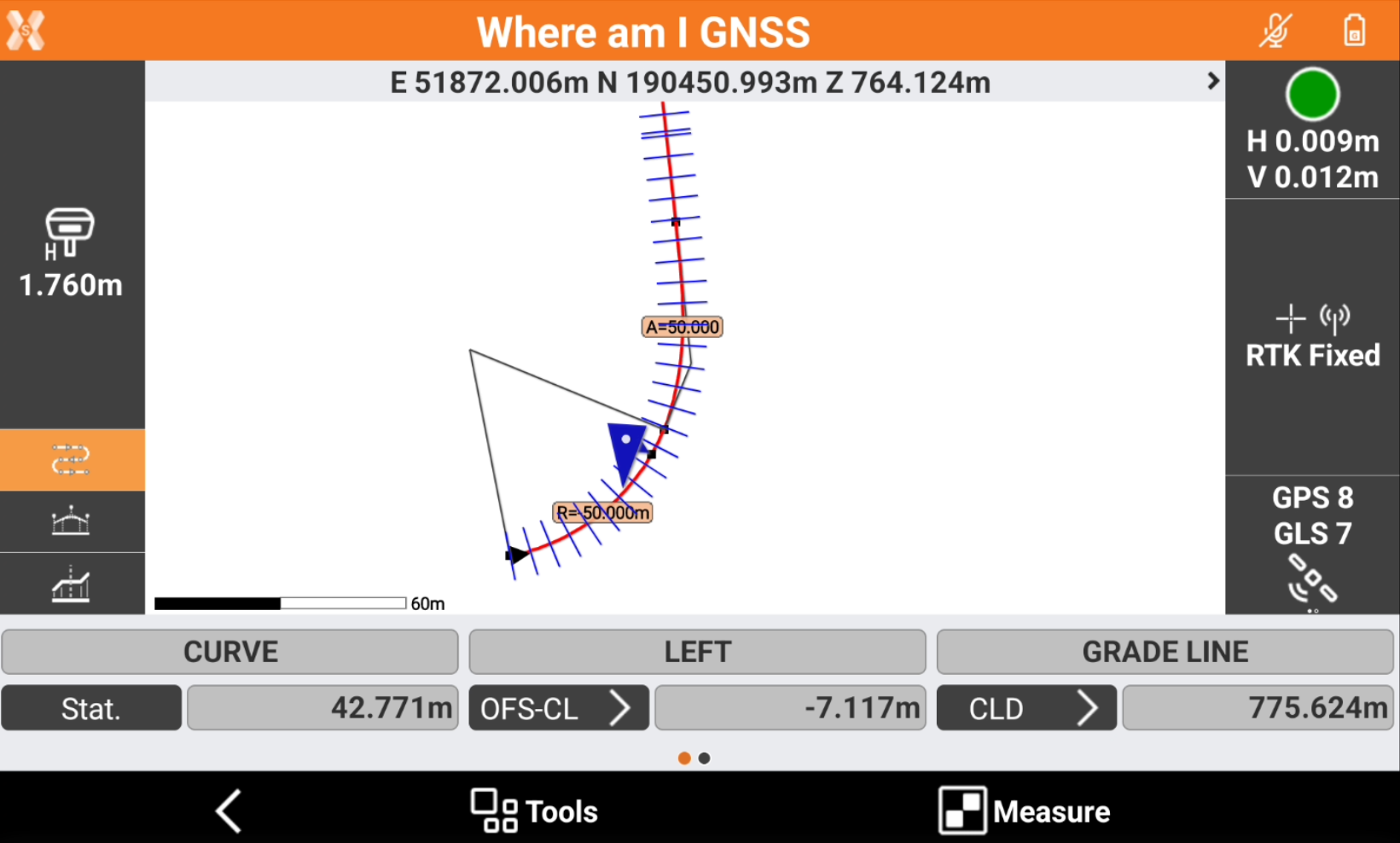
Based on the position, the following information are displayed.
Graphically visualization of the current position as plan view, profile view and cross section view.
Chainage of the current position.
Distance from the reference axis or a selected axis.
Element of the horizontal alignment.
Element of the vertical alignment.
Absolute elevation, axis elevation, elevation difference from the design.
Right or left side of the track.
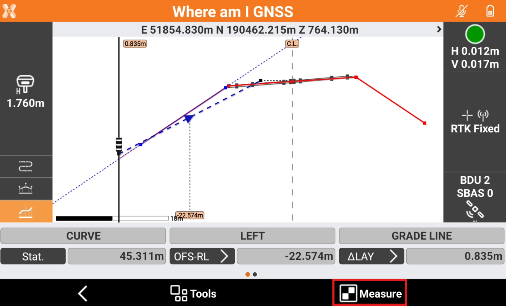
Where am I? toolbar
The bar shows different information related to the road design.
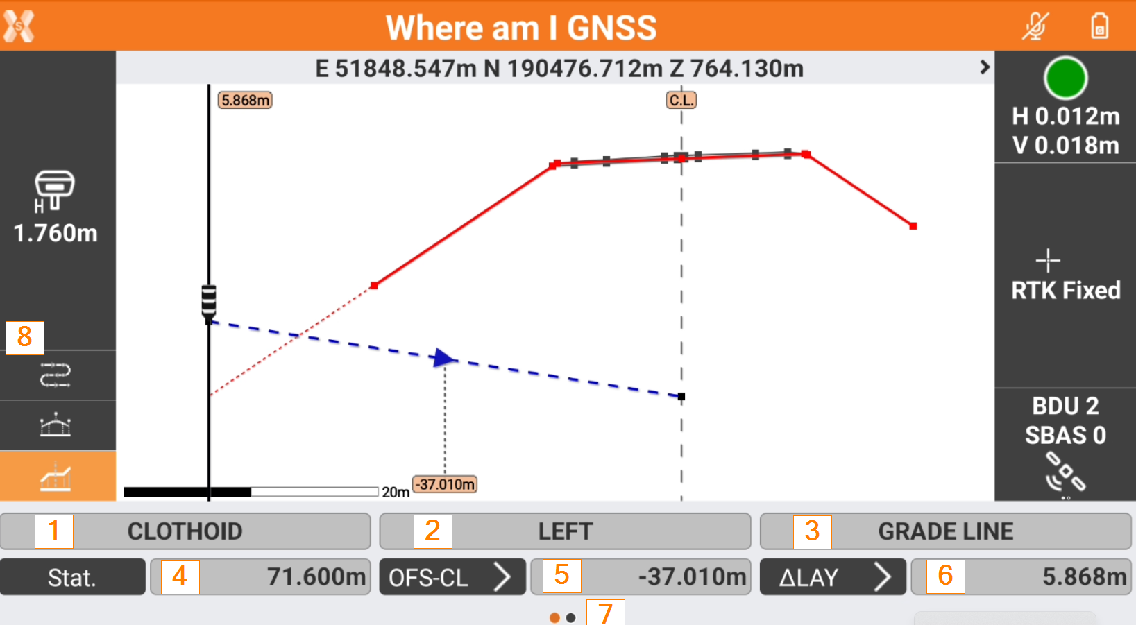
1: the element of the horizontal alignment at the current position.
2: shows if the current position is on the left or right side of the road.
3: the element of the vertical alignment at the current position.
4: current station.
5: horizontal offset from the reference element. Clicking the button it is possible to change the Offset mode.
6: difference elevation. Clicking the button it is possible to change the Elevation mode.
7: scroll the toolbar on the right to open the tools page.
8: change the view mode.
Change the view mode
On the left bar it is possible to change the view mode.
 : shows the current position over the horizontal alignment.
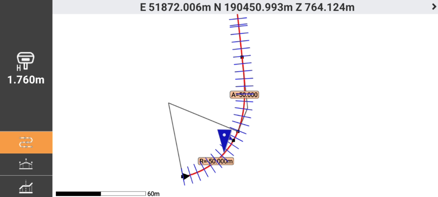
 : shows the current position (identified by the vertical black line) over the vertical alignment.
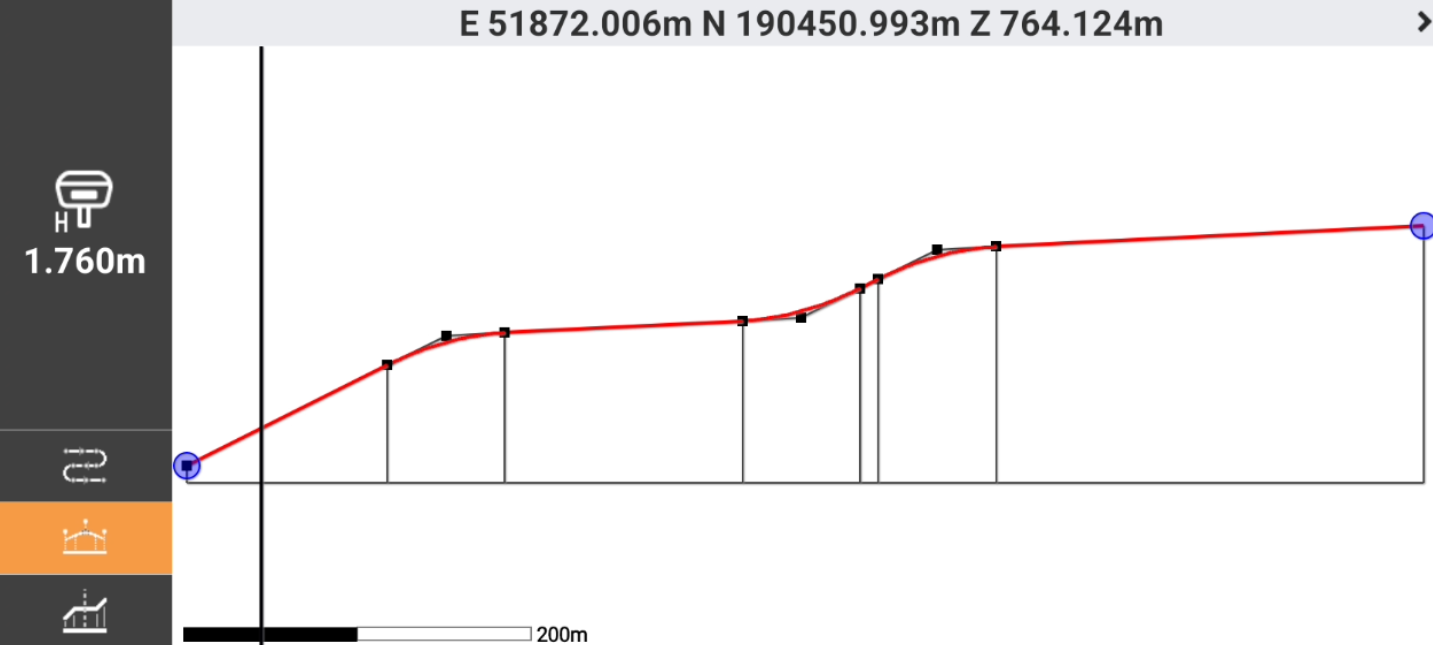
 : shows the current position over the cross section at the current station.
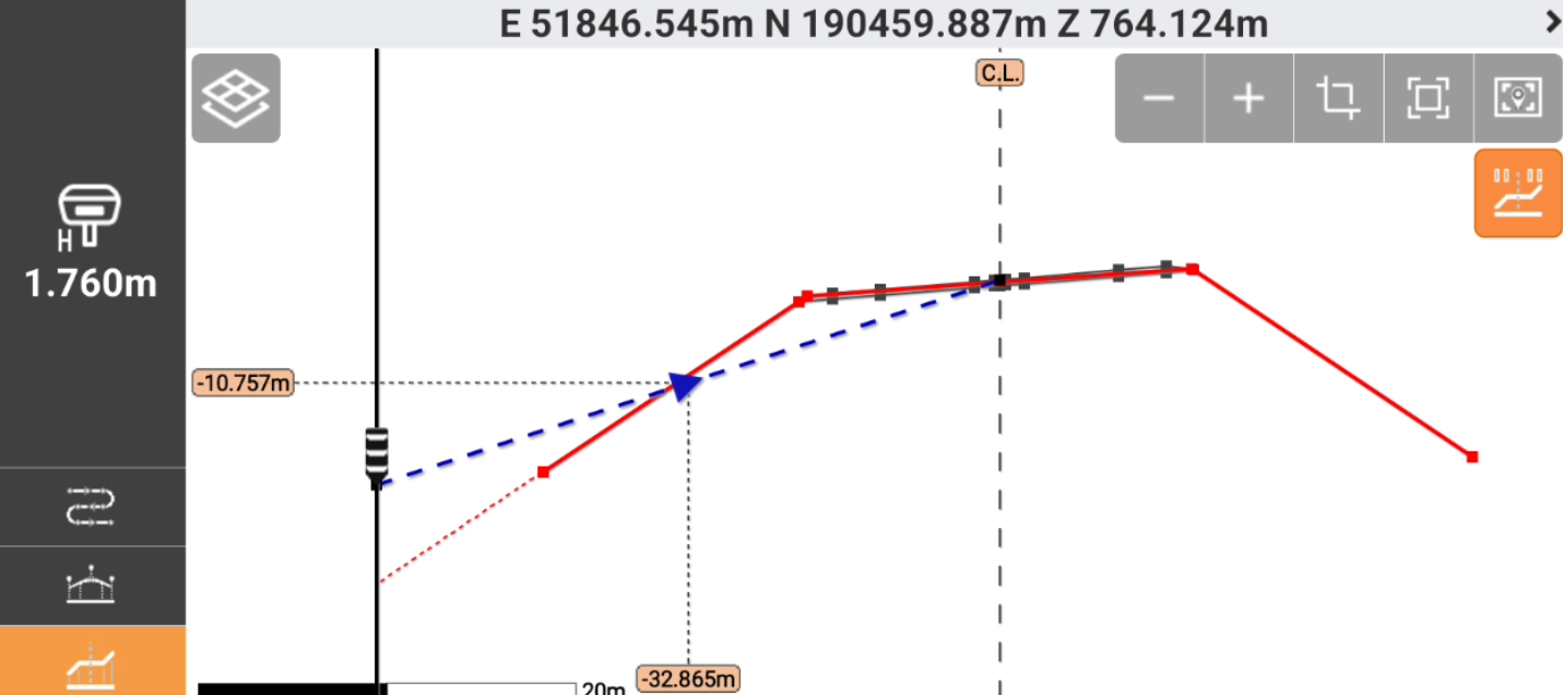
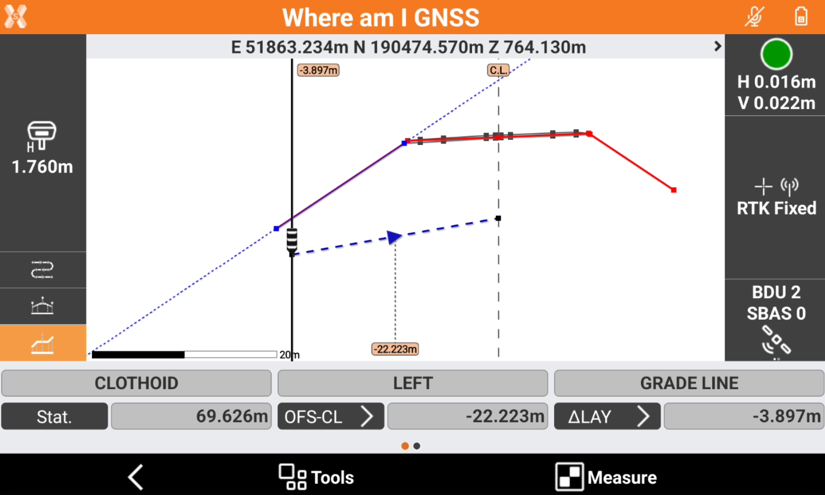
Offset value and offset mode
The function allows to stakeout the horizontal offset from the centerline or from a reference axis.
The information regarding the offset is available in the toolbar and on the graphic view when in cross section view.
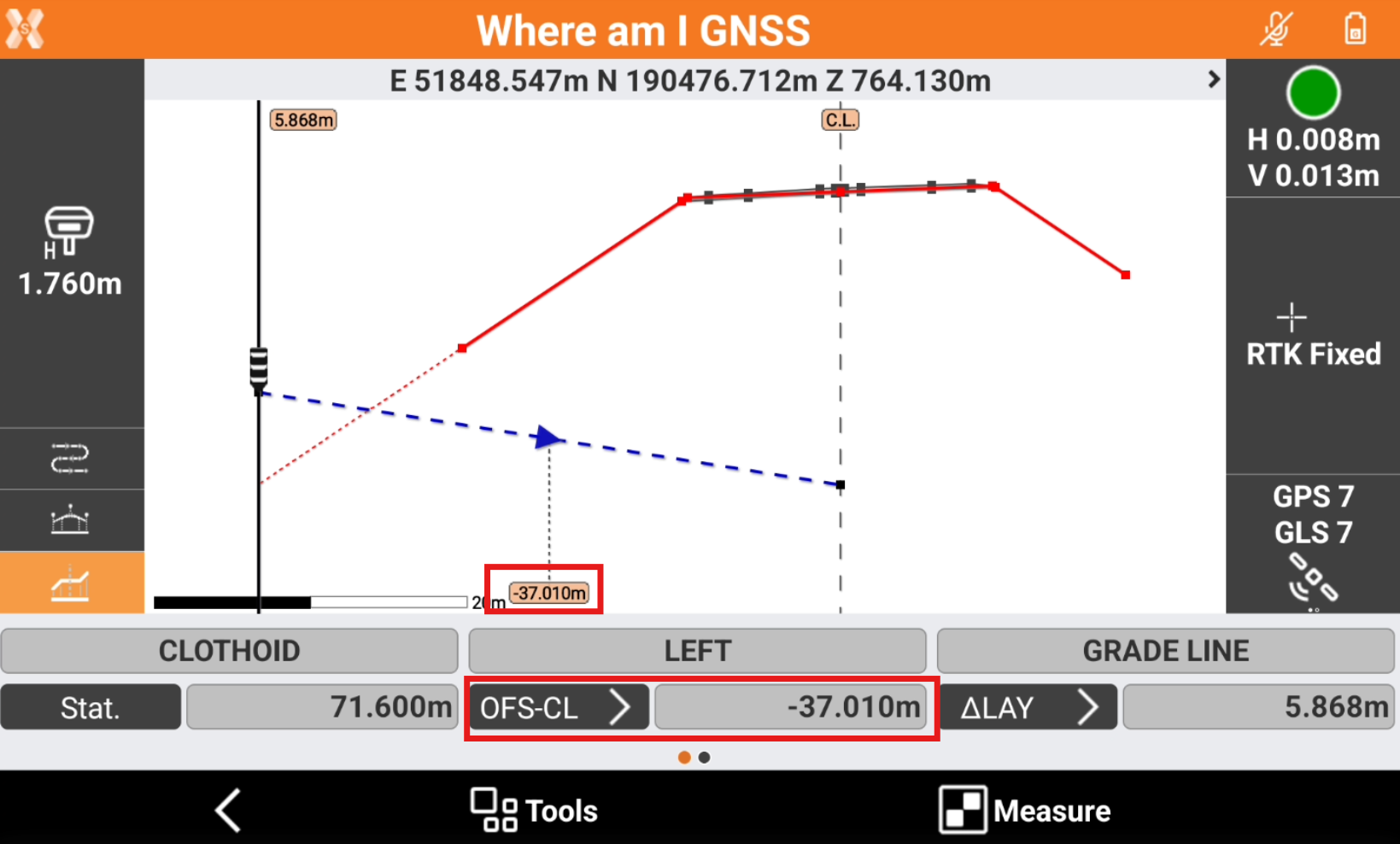
Clicking on the offset button in the toolbar it is possible to change the Offset mode.
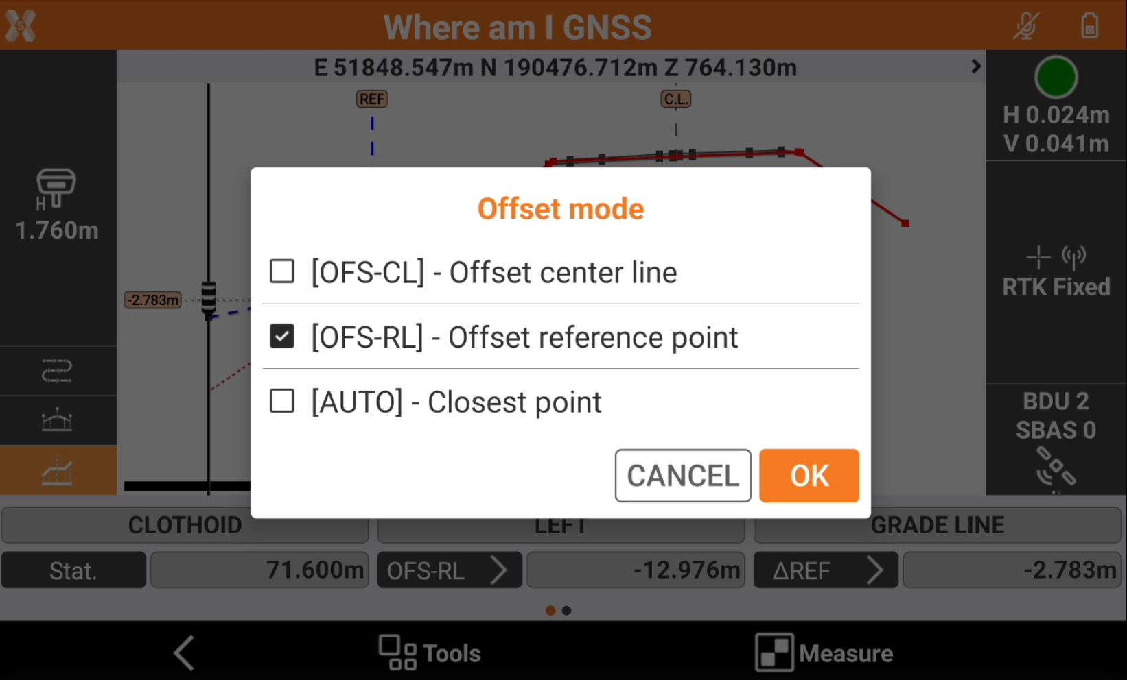
OFS-CL: the offset value is referred to the center line.
OFS-RL: the offset value is referred to the selected reference point. A reference point has to be selected.
AUTO: the software shows the offset automatically referring to the closest axis.
It is possible to select or change the reference point, for example when it is required to stakeout a different axis, clicking in the cross section view at a different vertex to change axis.
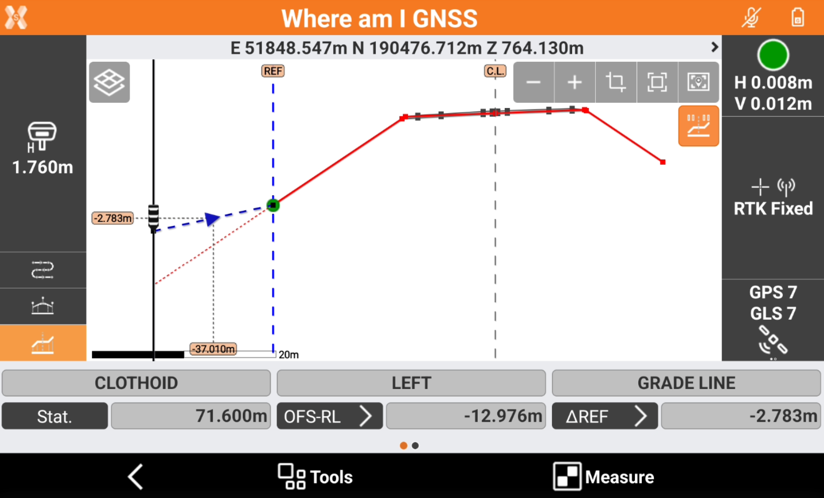
The offset is now to the selected reference point.
The selected reference point is visualized graphically with the label REF and the offset of the reference point is visible scrolling the toolbar on the right, as Ref.point.
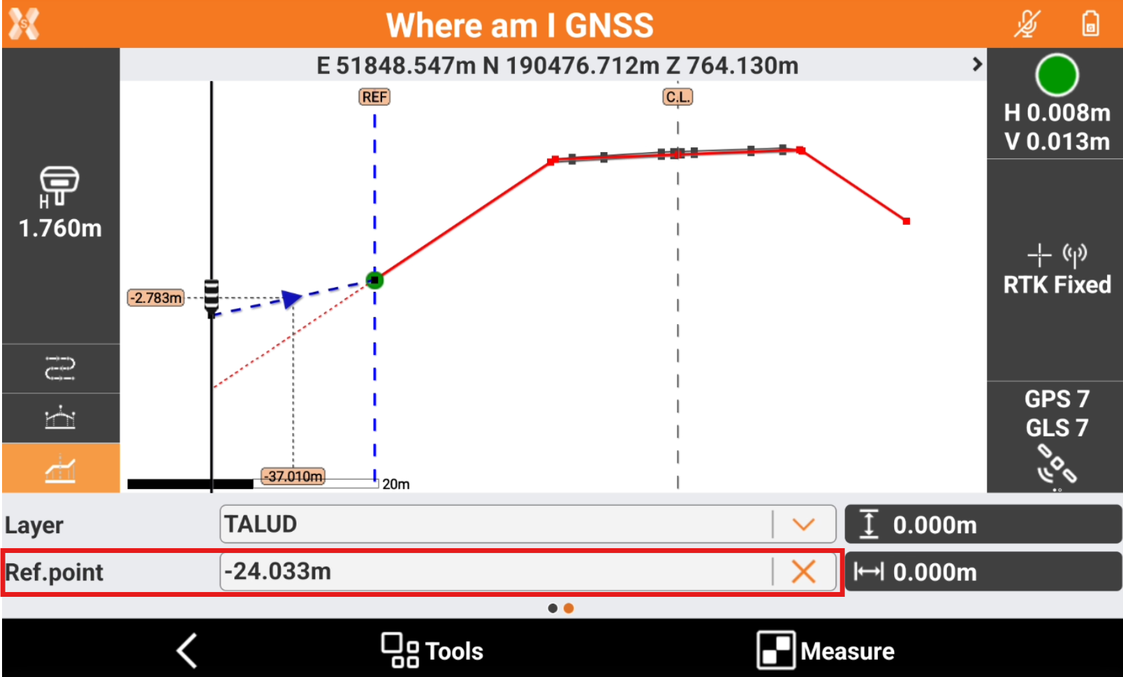
Click X to remove the current reference point or click to a different reference point in the cross section view to select a different one.
Below video shows how to change from centerline, to a reference axis and use the Offset mode commands.
Elevation difference and elevation mode
The function allows to stakeout the cross section and show the difference elevation to the design, to a reference point or to the centerline.
The information regarding the different elevation is available in the toolbar and on the graphic view when in cross section view.
The field shows the different elevation related to different road design elements. Click on the button to change the Elevation mode.
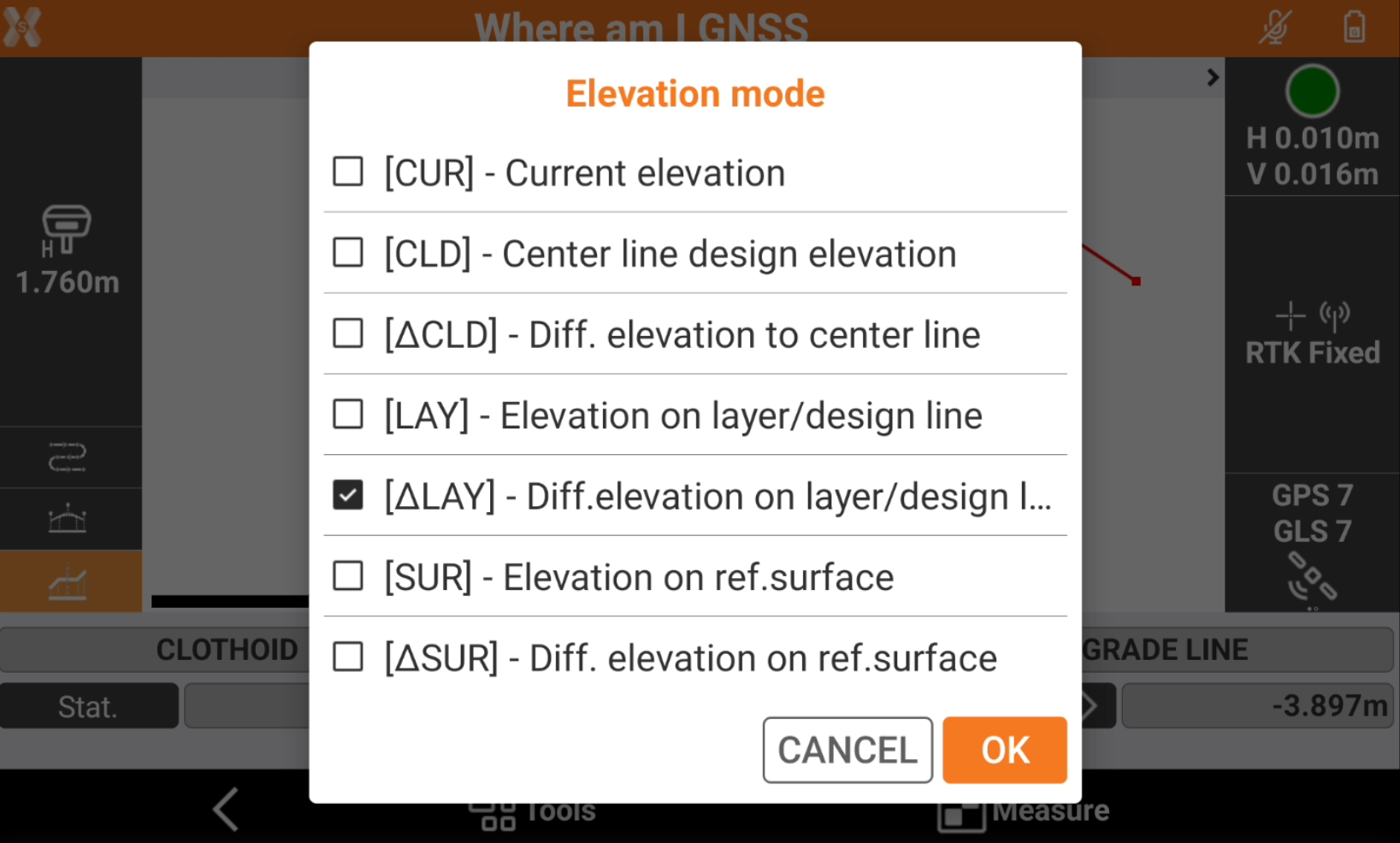
CUR: the current instrument elevation.
CLD: the elevation of the center line at the current station.
∆CLD: the different elevation from the current position to the center line at the current station.
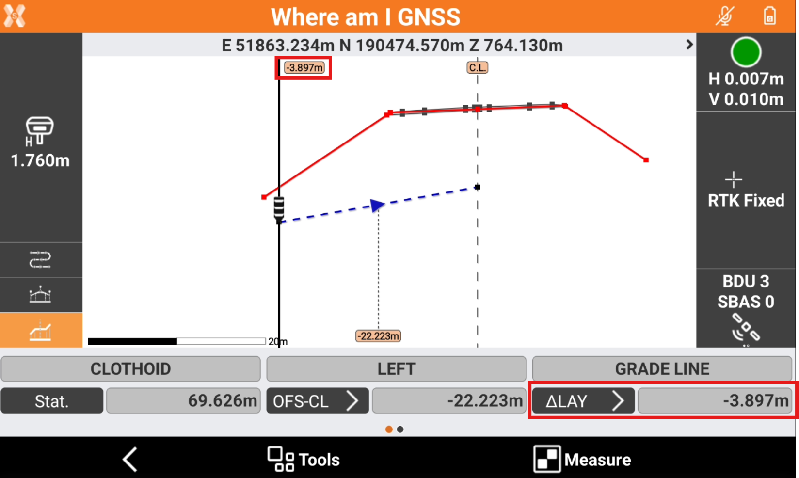
LAY: the elevation of the cross section at the current position.
∆LAY: the different elevation from the current position to the design cross section.
SUR: the elevation of the reference surface at the current position. Requires a reference surface to be loaded in Tools.
∆SUR: the different elevation from the current position to the reference surface. Requires a reference surface to be loaded in Tools.
It is possible to select a cross section segment to stakeout clicking in the cross section view on a specific segment.
The segment is visible in the graphic view with a blue dotted line.
The elevation difference is automatically changed to ∆LAY to display the different elevation to the cross section segment. When outside the segment, the software shows the difference elevation to the extension of the segment.
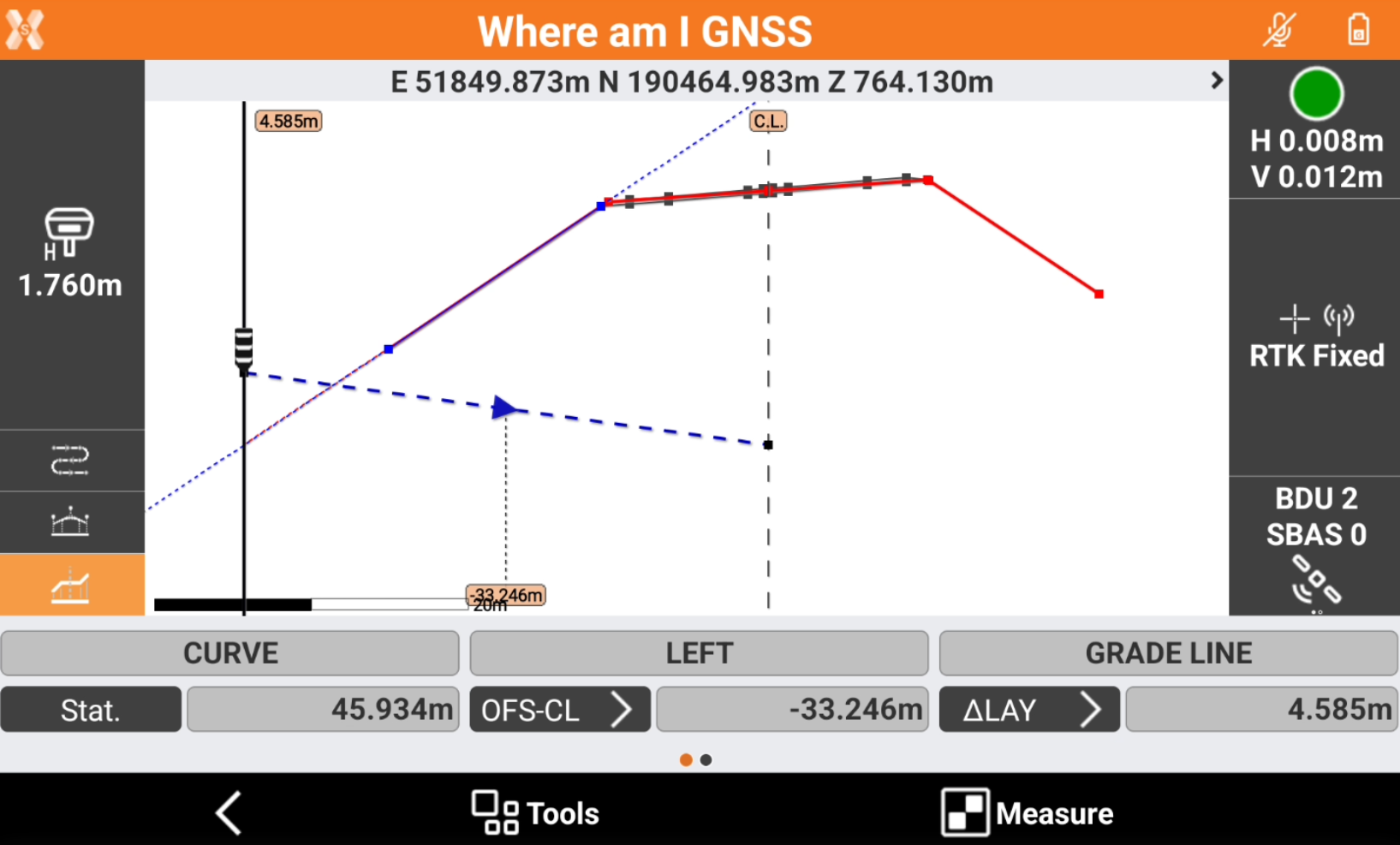
Below video shows how to change the Elevation mode and select a specific segment to stakeout.
Apply an offset
In the application it is possible to apply an horizontal or a vertical offset to the cross section.
To apply an offset scroll the toolbar to the right.
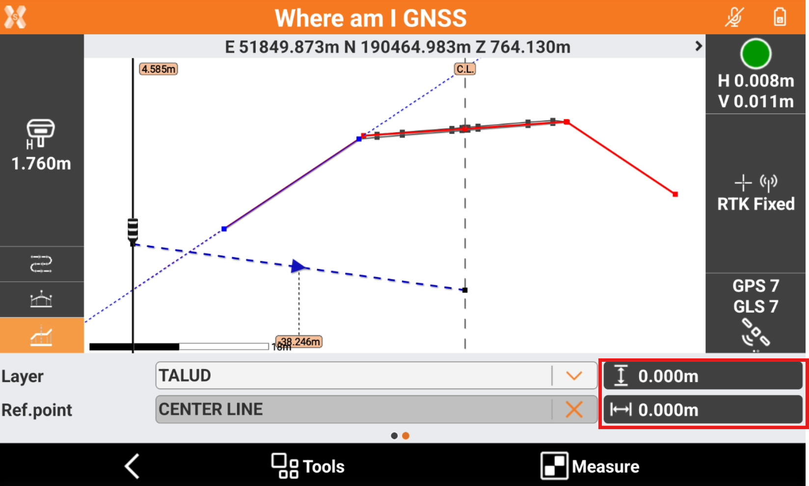
Select
 to enter a vertical offset to the cross section.
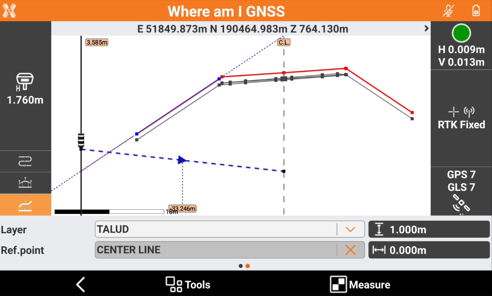
Select
 to apply an horizontal offset to a selected reference point. This option is only available if a reference point is selected.
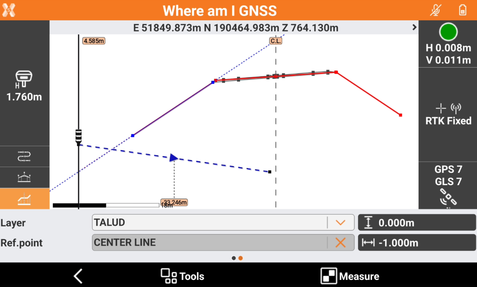
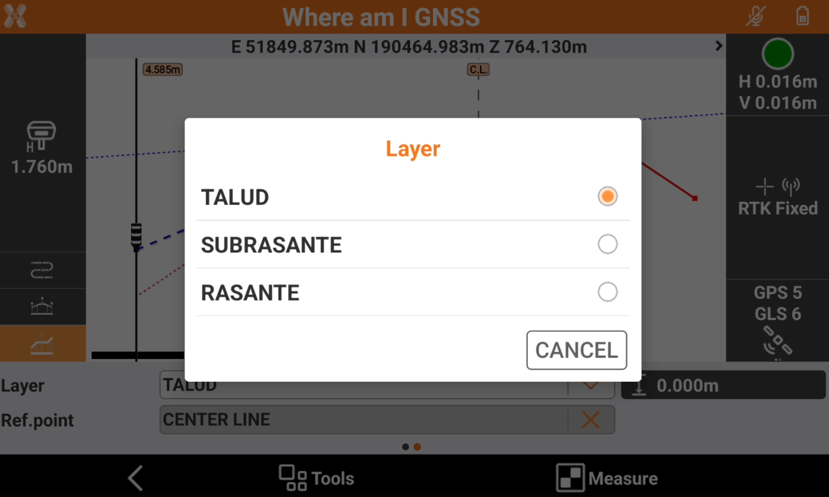
Change road design layer
Some data is available with multiple layers.
To select a different layer scroll the toolbar to the right and click Layer.
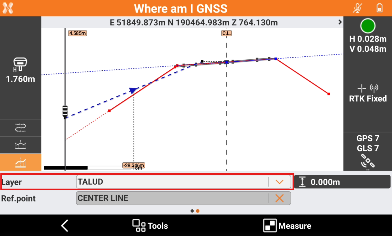
Select a different layer to stakeout.
Stakeout elevations on a reference surface
It is possible to stakeout elevations using a reference surface. The elevation will be calculated not on the road design but on the reference surface.
If a reference surface is used it is possible to change the Elevation mode to SUR and ∆SUR.
To load a surface click Tools and select Reference surface.
Select a surface from the list of available surfaces.
Measure a point
It is possible to record the position with the offset and elevation information.
To measure the current position with stakeout information click Measure.
The software records the position, entering the stakeout information in the description.
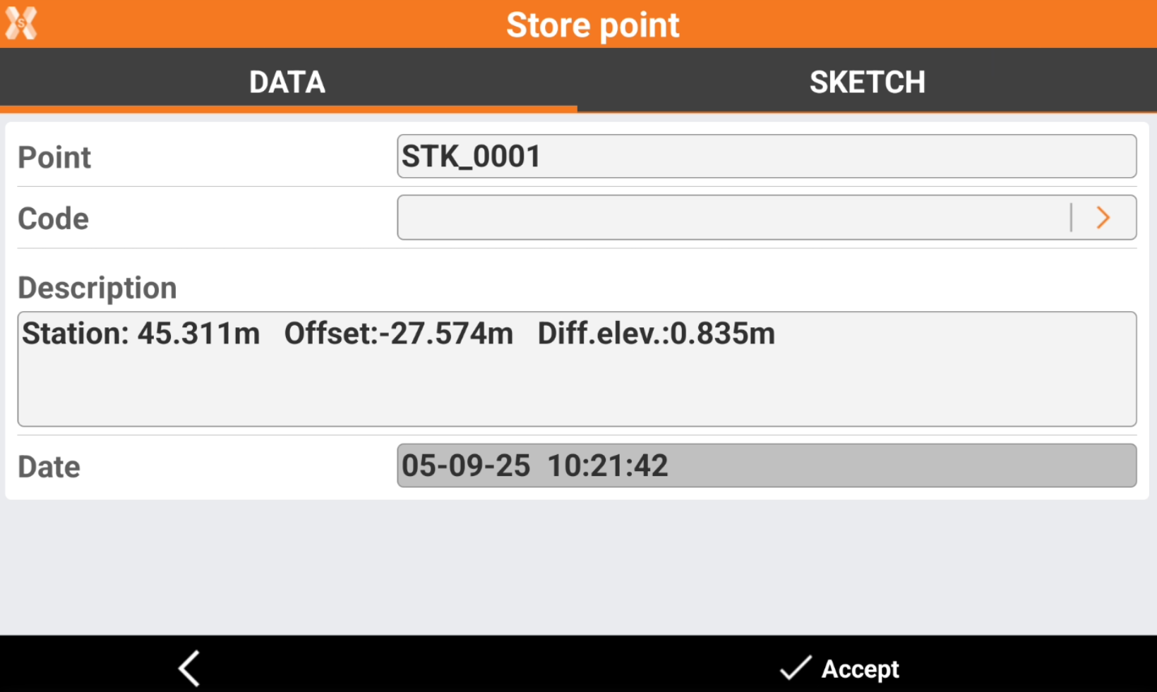
Click Accept to save the point.
The recorded point is available to be exported in the stakeout report.