Group of sections calculation rules
The calculation rules create the relationship between the source data and the section line.
The calculation rules allow to improve the understanding of the work even after certain time, to memorize in the work the relationship between subprojects and the section lines and the parameters of generation, to simplify the updating of the sections. This allows, for example, after certain time or to an operator who doesn’t know the job of updating the work.
It is possible to define different calculation rules for the cross sections and the longitudinal profile.
A section or topographic profile may be calculated from the following sources:
Surface: uses triangles of the surface subproject.
Point clouds: uses the elements of the point clouds.
Points: uses the topographic points in the selected survey subproject.
Survey drawing (line, polylines, …): uses the lines and polylines of the survey drawing.
Breaklines: uses only the breaklines in the selected surface subproject.
Solid ortophoto: uses available solid ortophotos.
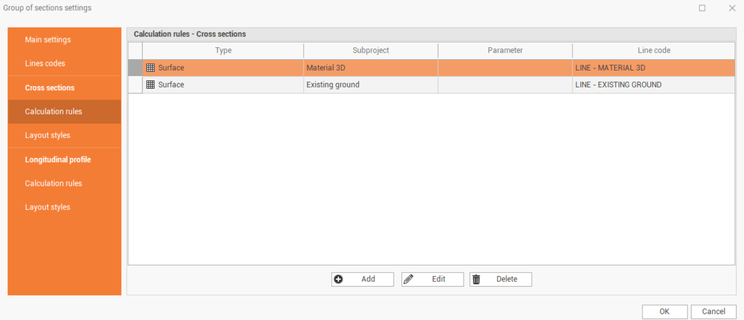
In the window each row describes a set calculation rule and its properties:
Type: the type of calculation set for the item.
Subproject: the reference subproject from which the element extracts data.
Line code: the line code that the calculation rule will generate.
The commands allow to modify the rules:
Add: creates a new calculation rule.
Edit: modifies an existing calculation rule.
Delete: deletes a calculation rule.
Pressing the Add or Edit button shows a window in which you can define the source of the calculation; the options available depend on the type of model used for the calculation.
Calculation from surface
The command calculates section lines based on the intersection of the section with the surface triangles.
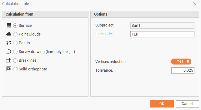
The setting enables the following options:
Subproject: sets the subproject of surfaces to be used to calculate the line.
Line code: sets the code of the section element to create.
Vertices reduction: toggles an automatic reduction in the number of vertices based on the Tolerance of alignments set. The procedure analyzes all the vertices of the calculated section line and deletes all those that are aligned and therefore does not generate any useful intersections. If the perpendicular distance of a point from the alignment, consisting of the previous and next point, is less than the tolerance, this is not considered useful and is deleted.
Tolerance: sets the value of the vertex alignment tolerance.
Calculation from point clouds
The command calculates section lines based on the intersection of the section with the point cloud.
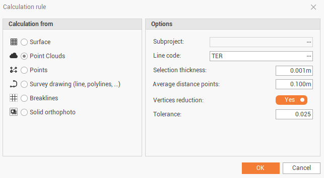
The setting enables the following options:
Subproject: sets the subproject of point clouds to be used to calculate the line.
Line code: sets the code of the section element to create.
Selection thickness: sets the thickness of the selection band to use to extract the points that will be used to calculate the section line.
Average distance points: sets the average distance of point clouds points to stop the calculated section line correctly.
Vertices reduction: toggles an automatic reduction in the number of vertices based on the Tolerance of alignments set. The procedure analyzes all the vertices of the calculated section line and deletes all those that are aligned and therefore does not generate any useful intersections. If the perpendicular distance of a point from the alignment, consisting of the previous and next point, is less than the tolerance, this is not considered useful and is deleted.
Tolerance: sets the value of the vertex alignment tolerance.
Calculation from points
The command calculates section lines based on the intersection of the section with the topographic points within a selection strip.
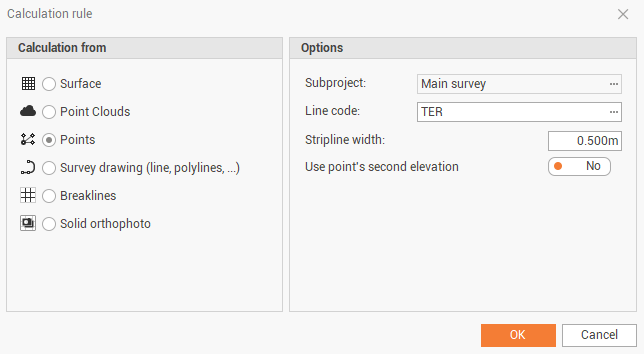
The setting enables the following options:
Subproject: sets the subproject of survey to be used to calculate the line.
Line code: sets the code of the section element to create.
Stripline width: sets the width of the selection strip to use to extract the points to be calculated. Only the points inside the selection range will be used for calculating the section line.
Use point’s second elevation: enables/disables the use of the second elevation of points instead of the elevation.
Calculation from survey drawing
The command calculates section lines based on the intersection of the section with the elements of the survey drawing.
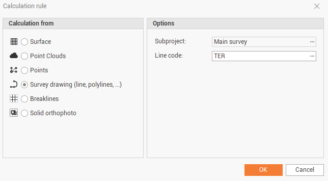
The setting enables the following options:
Subproject: sets the subproject of survey to be used to calculate the line.
Line code: sets the code of the section element to create.
Stripline width: sets the width of the selection strip to use to extract the points to be calculated. Only the points inside the selection range will be used for calculating the section line.
Use point’s second elevation: enables/disables the use of the second elevation of points instead of the elevation.
Calculation from breaklines
The command calculates section lines based on the intersection of the section with surface breaklines.
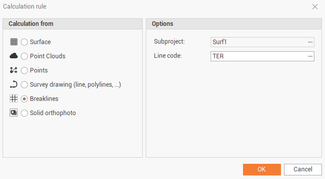
The setting enables the following options:
Subproject: sets the subproject of surface to be used to calculate the line.
Line code: sets the code of the section element to create.
Calculation from solid orthophoto
The command calculates section lines based on the intersection of the section with solid orthophoto.
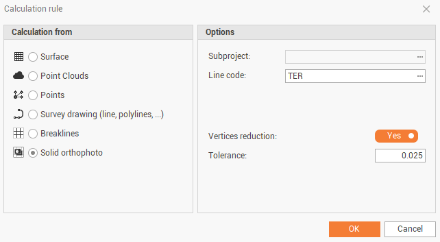
The setting enables the following options:
Subproject: sets the subproject of surface to be used to calculate the line.
Line code: sets the code of the section element to create.
Vertices reduction: toggles an automatic reduction in the number of vertices based on the Tolerance of alignments set. The procedure analyzes all the vertices of the calculated section line and deletes all those that are aligned and therefore does not generate any useful intersections. If the perpendicular distance of a point from the alignment, consisting of the previous and next point, is less than the tolerance, this is not considered useful and is deleted.
Tolerance: sets the value of the vertex alignment tolerance.