Clipping planes
Clipping planes are used to hide external elements from the predefined planes.
They can be saved in the Project Manager, with a maximum of five clipping boxes allowed.
Define a clipping plane
Click View.
Click Clipping plane:
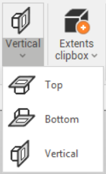
Top: hides all data above the selected plane. Select the upper clipping elevation in the graphic window.
Bottom: hides all data below the selected plane. Select the lower clipping elevation in the graphic window.
Vertical: creates a vertical plane based on two points defining the direction. All data to the right of the plane will be hidden. Select the first and second point in the graphic window to define the direction of the plane.
When a clipping plane is created, it is automatically saved in the Project manager under Clipping planes and boxes.
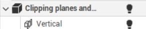
Turn on/off a clipping plane
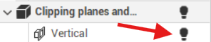
A clipping plane can be easily turned On/Off from the Project manager.
Click on light icon in the Project manager to turn it on and off.
Delete a clipping plane
A clipping plane can be deleted from the Project manager.
Right-click on the clipping plane and select Delete.
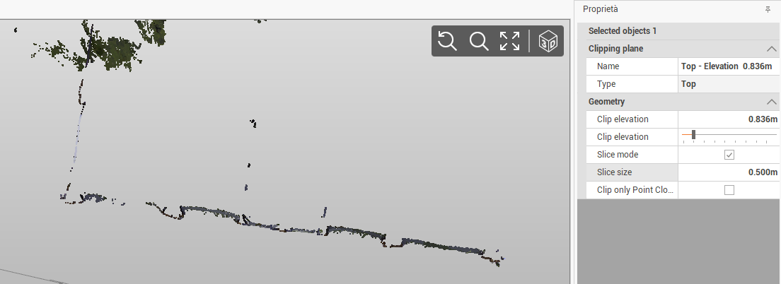
Clipping plane properties
Clipping plane are useful to create slices of point clouds, to help for example in drawing over a point cloud or to hide part of a point cloud.
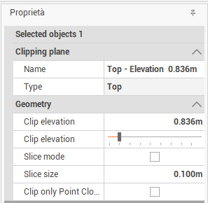
Once a clipping plane has been saved, selecting it from the Project manager, opens the property table, where you can adjust the following settings:
Clip elevation: sets the elevation of the clipping plane (top or bottom type).
Clip plane position: adjusts the position of the vertical clipping plane.
Slice mode: creates a slice of the view.
Slice size: defines the thickness of the slice.
Clip only Point Cloud: selects if the clipping plane affects all entities in the project or only the point clouds.
Slice mode
Slice mode is particularly useful when drawing over a point cloud
Create the clipping plane and save it.
Open the property page of the clipping plane.
Activate the Slice mode.
Define the size of the slice to visualize the slice of point cloud data only.