Create a topographic cross section on 2 surfaces step-by-step
In this example we will see how to create cross sections lines and generate the output starting from 2 surfaces.
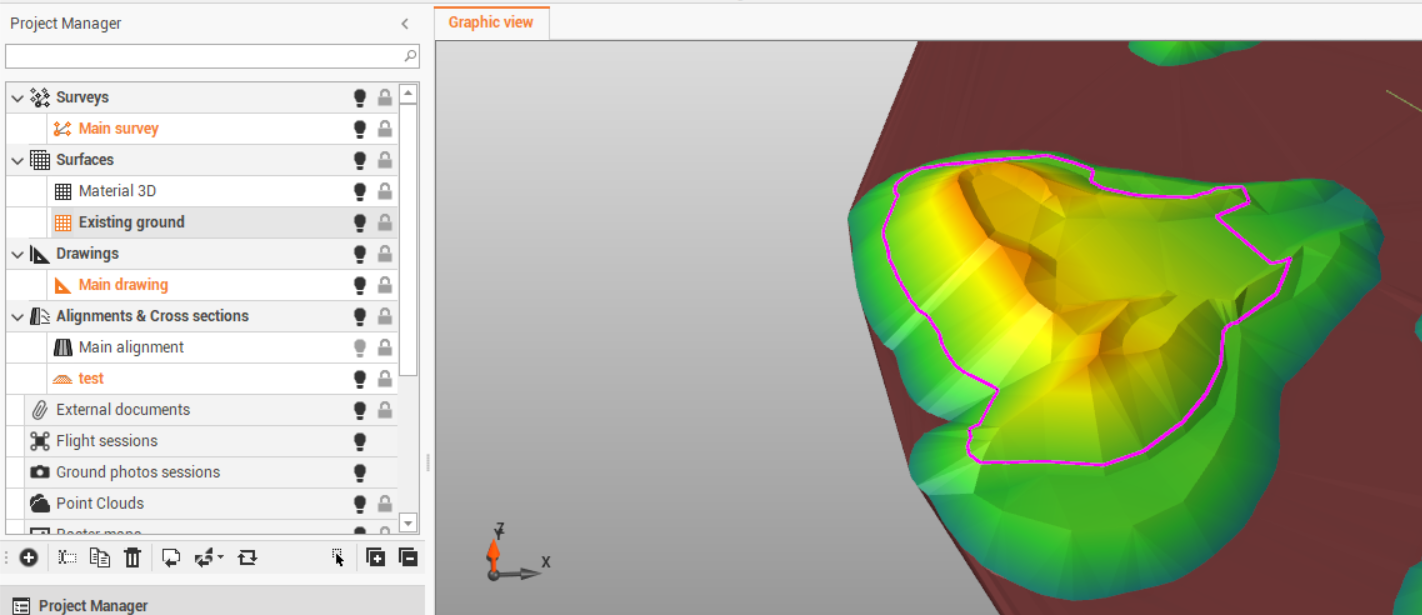
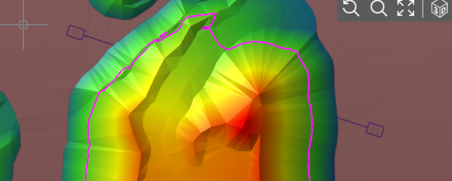
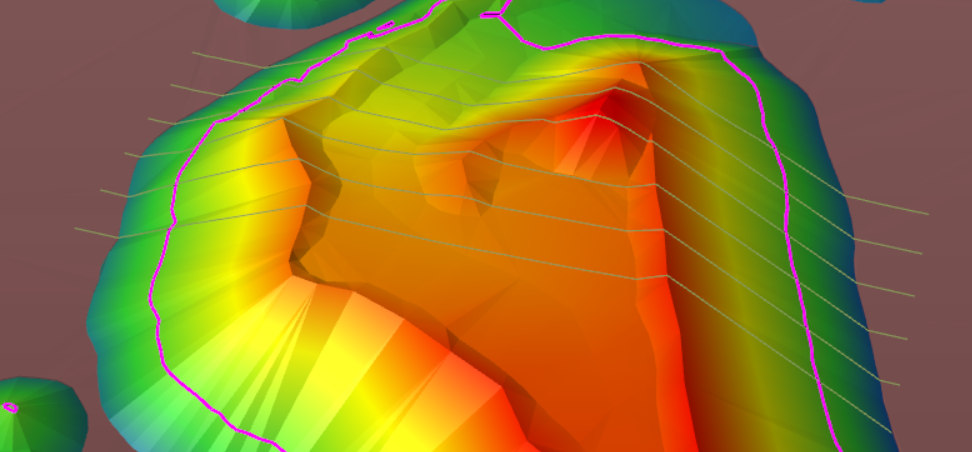
We start from two surface as separate subprojects. Existing ground (in brown) is below the Material 3D surface (colored by elevation).
Within the Alignments & x-sections toolbar, click New Sections group and select to create Topographic cross sections.
Click Topographic to create the first topographic cross section.
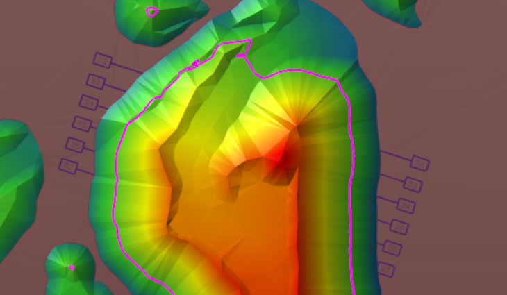
Now we can create parallel cross sections using the function Offset.
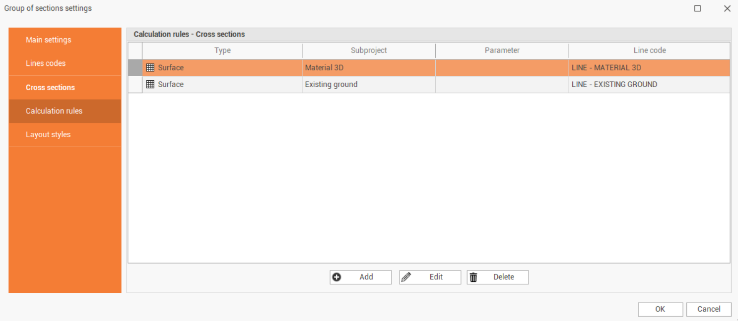
Click Settings and Calculation rules to verify the rules are correct. The rule has to be that both surfaces are used to calculate the cross section, and in two different line codes.
Click Calculate to calculate all cross sections.
Click Cross sections to open the cross section view.
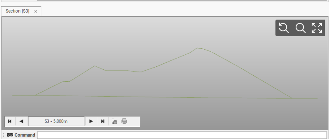
Within the cross section view click on Layout mode to open the layout view.
We can change the reference elevation of the cross section in the Cross section table.
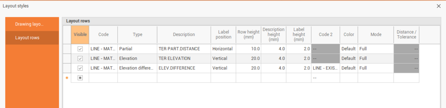
In the Settings, in the Layout Style tab we can customize the Layout rows to plot.
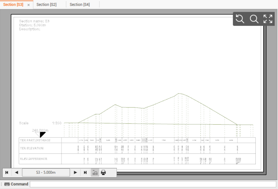
If for example we want to show the different elevation between the 2 cross sections, we can select Elevation difference as Type, and select the codes used for the two cross sections in Code and Code 2 columns.
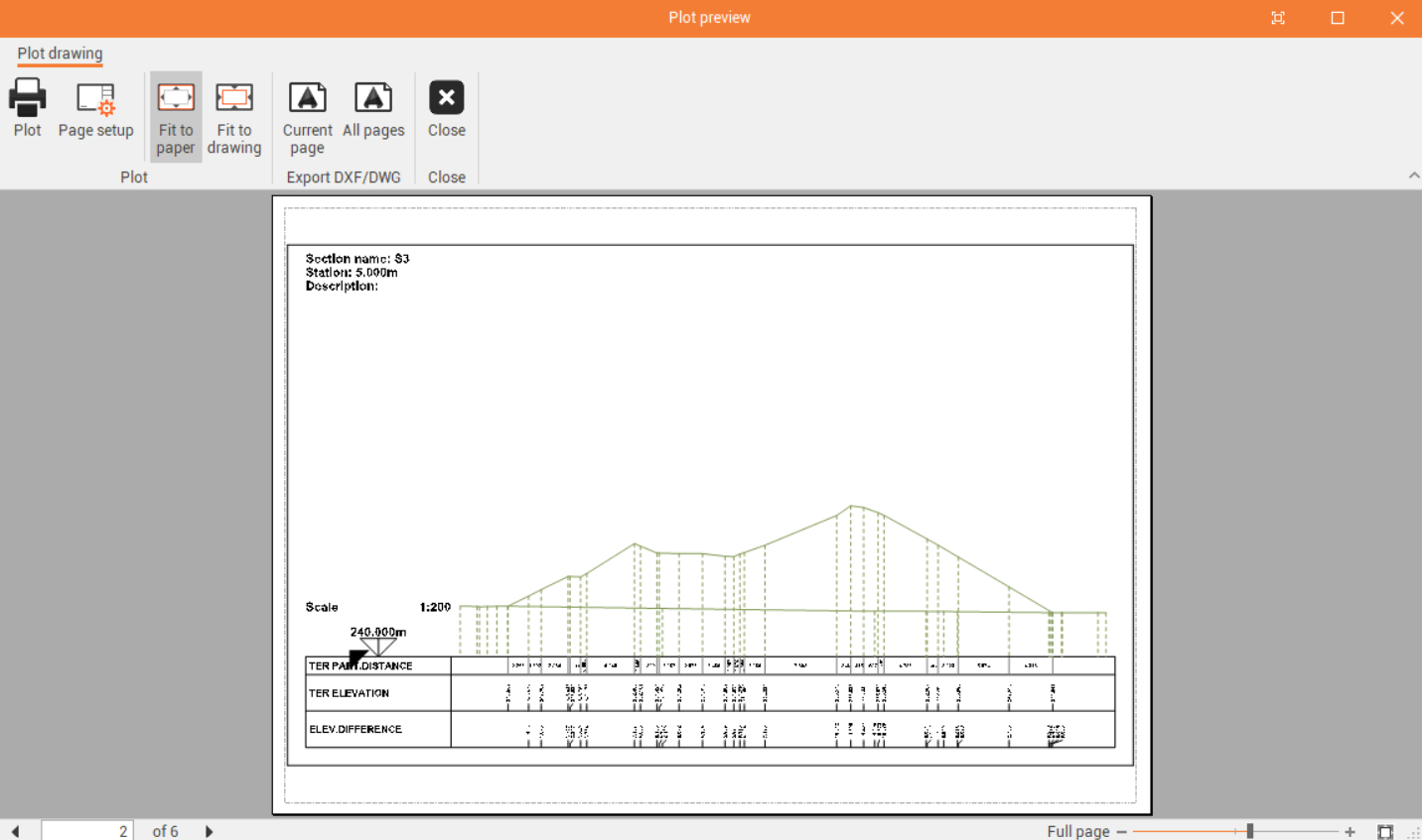
This is the result in the Layout.
In the Output toolbar, click on Cross Sections to plot the cross section or click DWG/DXF to export the cross section, in the CAD view or layout view, to AutoCAD formats.