Group of sections layout styles
In the tab Layout Styles, you can set the set of features that serve to create the final drawing including the page size, the size of the texts, the lines and the table at the bottom of the drawing.
You can create different types of layout style to be applied as needed, for example when changing the representation scale of the section.
It is possible to define different calculation rules for the cross sections and the longitudinal profile.
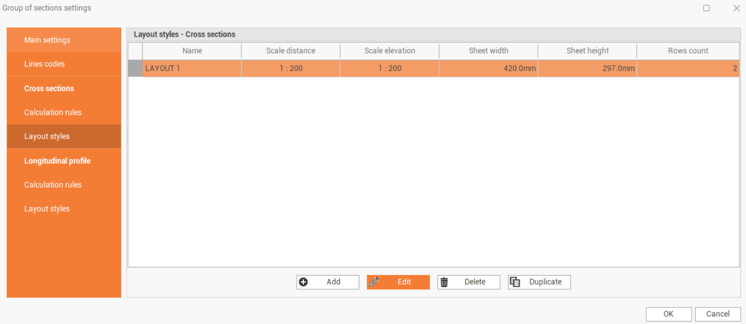
The tab allows you to view the following data in the table:
Name: the name of the style.
Scale distance: the scale set for the x-axis representation.
Scale elevation: the scale set for representing the ordinates.
Sheet width: the width of the single section sheet.
Sheet height: the height of the single section sheet.
Rows count: the number of rows in the layout style table.
The commands allow to add and modify the layout styles.
Add: creates a new layout style.
Edit: edits an existing layout style. You can also change the style even with the double click on the table row.
Delete: deletes the selected layout style.
Duplicate: duplicates the selected layout style.
Creating and editing of a layout style
By pressing the Add or Edit button on the toolbar, the program shows a window where you can set all the parameters for creating the layout style and managing its lines.
The section drawing layout is only visible in layout mode.
The window splits into two tabs.
The Drawing layout page allows to edit the layout dimensions and styles.
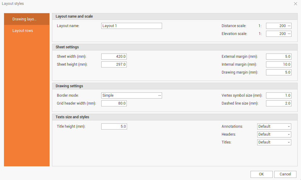
Layout name: the name of the layout style.
Distance scale: sets the scale set for the x-axis representation.
Elevation scale: sets the scale set for y-axis representation.
Sheet width (mm): sets the width of the single section sheet.
Sheet height (mm): sets the height of the single section sheet.
External margin (mm): sets the external margin of the sheet.
Internal margin (mm): sets the internal margin of the sheet.
Drawing margin (mm): sets a margin between the drawing of the section and the drawing layout.
Border mode: allows to choose the drawing type of the drawing boarder. The drawing type can be Simple, Double or Corners.
Grid header width (mm): sets the width of the header lines of the layout style.
Vertex symbol size (mm): sets the size of the vertex symbol of the elements. To turn on the display of the symbol see Group of sections lines codes settings.
Dashed line size (mm): sets the size of the dash.
Title height (mm): sets the height of the section title.
Annotations: set the dimensioning style using the set text styles.
Headers: set the style of the headers using the text styles set.
Titles: set the style of the titles using the text styles set
The Layout rows displays the settings that generate the layout drawing lines. In the table you can set the type of row to display and its properties.
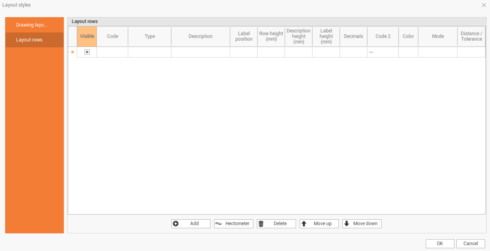
Visible: show/Hide the drawing layout.
Code: allows to choose the code of the section line to be dimensioned.
Type: allows to choose the type of data to display.
Point number: if the section line is calculated from the topographic points it is possible to Annotation row the name of the point.
Coordinates X: displays the east coordinate of the section line vertices.
Coordinates Y: displays the northern coordinate of the vertices of the section line.
Elevation: displays the elevation of section line vertices.
Station: displays the horizontal progressive distance of the vertices of the section line.
Station sloped: displays the sloped progressive distance of the section line vertices.
Partial: displays the partial horizontal distance between the vertices of the section line.
Partial sloped: displays the sloped distance between the vertices of the section line.
Slope: displays the slope between the vertices of the section line.
Height difference: displays the height difference between the vertices of the section line.
Elevation difference: allows to perform the difference of elevation between 2 lines of section with different codes. To perform the operation, you must input the code of the comparison section line in the cell Code 2.
Description: sets the text to be displayed in the drawing layout.
Label position: allows to choose the orientation of the dimension text.
Row height (mm): sets the row height.
Description height (mm): sets the height of the description text.
Label height (mm): sets the height of the dimension labels.
Decimals: number of decimals for labels.
Code 2: allows to select the section line comparison code to use for the Type selection Height difference.
Color: sets the color of the annotation row. The possible options are:
Default: sets the default color of the drawing layout.
Line: set the same color as the section line.
The commands allow to edit the layout rows.
Add: creates a new row of drawing layout.
Hectometer: adds a new row of drawing layout with the representation of distance as Hectometer.
Delete: deletes a row of drawing layout.
Move up: moves the selected row upward.
Move down: moves the selected row down.