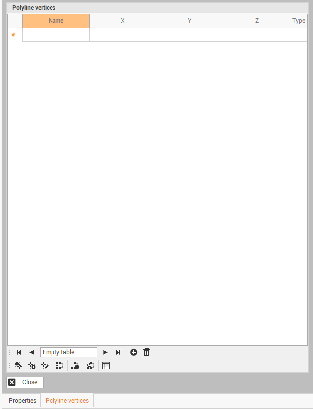
Polyline by vertices grid
Use the command Polyline by vertices grid to create a polyline entering the vertex coordinates in a grid.
Click Draw.
Click below Polyline to open drop down menu.
Click Polyline by vertices grid.
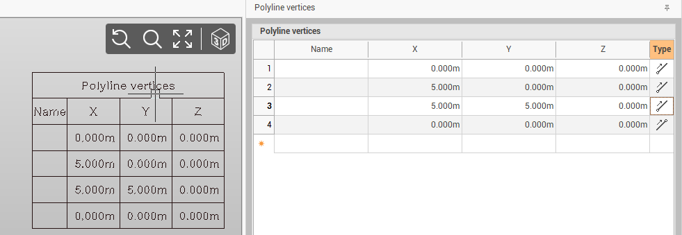
This function opens a table on the right side of the window.
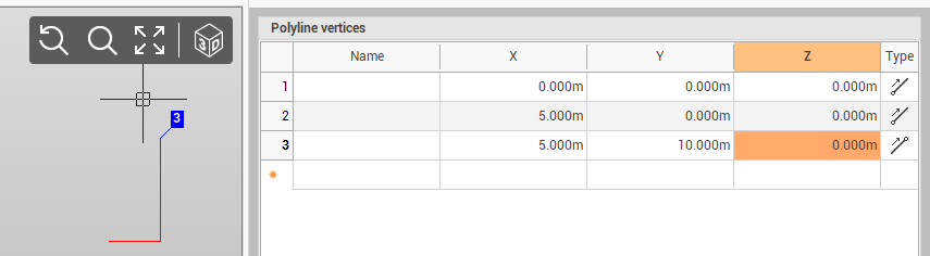
Enter the coordinates of polyline vertices directly in the table. The polyline is visualized in the graphic view in real time.
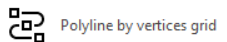
On the bottom bar there are some commands to help to create the table:
Insert
 : inserts a new line in the table.
Delete
 : deletes selected line.
Add vertex before
 : adds a new vertex before the selected vertex in the table. Click on graphic view to create the new vertex.
Add vertex after
 : adds a new vertex after the selected vertex in the table. Click on graphic view to create the new vertex.
Edit vertex
 : changes the coordinate of selected vertex in the table. Click on graphic view to edit the current vertex.
Close
 : closes the polyline creating a point at the end of table.
New polyline
 : creates a new polyline.
Invert
 : inverts the polyline direction.
Insert table
 : creates the table in the CAD.