
Use the Vertices grid function to open an editable table with the vertex coordinates of the selected polyline.
-
Click Edit.
-
Click Vertices grid.

-
Select a polyline.
-
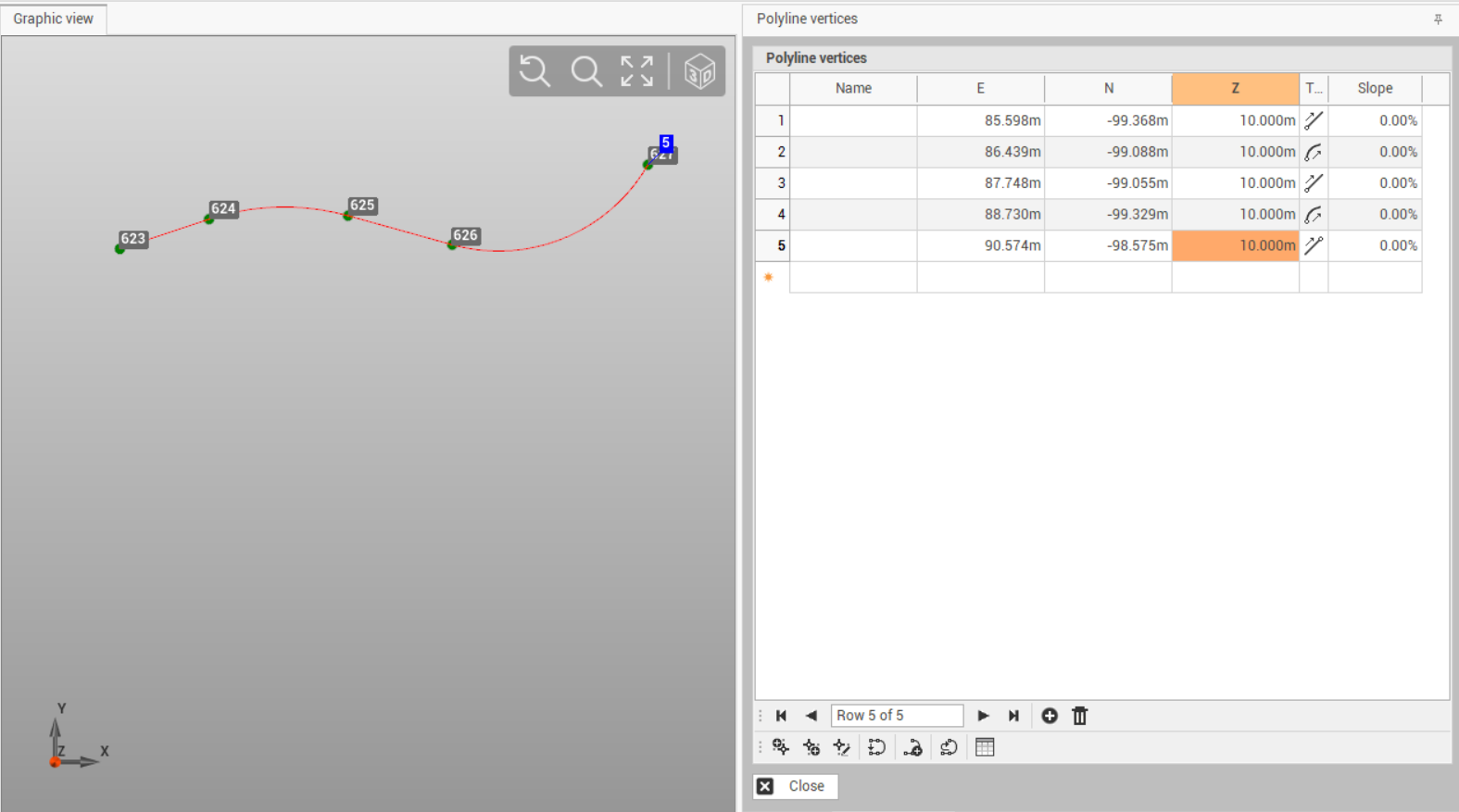
The function opens a atable on the right panel.
-
The table can be edited to change the vertexes of the polyline.
-
Name: the name of the vertex point.
-
E, N, Z: the coordinate of the vertex.
-
Type: the type of the segment starting from the vertex, for example line or arc.
-
Slope: the slope to the next vertex, edit this field to automatically recalculate the new elevation.
-
Insert: to insert a new vertex in the table.
-
Remove: to remove the selected table line and corresponding vertex.
-
Add vertex before: to add a new vertex before the selected line. Click on the graphic view to create the new vertex.
-
Add vertex after: to add a new vertex after the selected line. Click on the graphic view to create the new vertex.
-
Edit vertex: to edit the selected vertex from the CAD.
-
Close: to close the polyline.
-
New polyline: to create a new polyline and a new vertex table.
-
Invert polyline: to invert the order of the polyline vertexes.
-
Table: to create a drawing table of the polyline. Click on the graphic area to insert the table.
-