
-
The polylines in the sections are called Section lines and are generated by the calculation procedure. These have a code that represents them; the code is used to perform automatic dimensioning in the section layout. It is also used to describe a feature of the section and to uniquely identify the section line.
-
The calculation rules define the relationship between each Section Line and the data by which it was generated (survey, surfaces, point clouds).
-
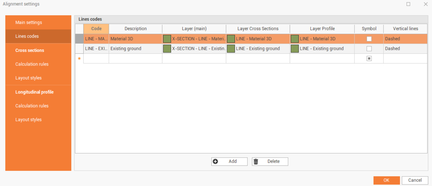
In the tab Lines Codes you can create the polyline codes to use when creating rules.
-
Code: line identification code.
-
Description: associated description.
-
Layer (main): the layer used to represent the lines in the graphic view of the planimetry.
-
Layer cross sections: the layer used to represent the lines in the section view.
-
Layer profile: the layer used to represent the profile secion.
-
Symbol: symbol on the vertices of the section line in Layout mode.
-
Vertical lines: type of lines for section element vertex dimensioning. If an option is selected, a vertical stroke is drawn on each vertex of the line.
-
Add: adds a new code.
-
Delete: deletes a code and all its properties.