Volume calculation to reference plane
The program can calculate cut and fill volumes between the Surface and a reference plane defined according to different way. The datum plane can be both tilted and horizontal and the calculation of the areas can be performed so that the cut and fill volumes are balanced.
Click Surfaces.
Click Calculate.

Select To reference plane
This command opens a panel on the right.
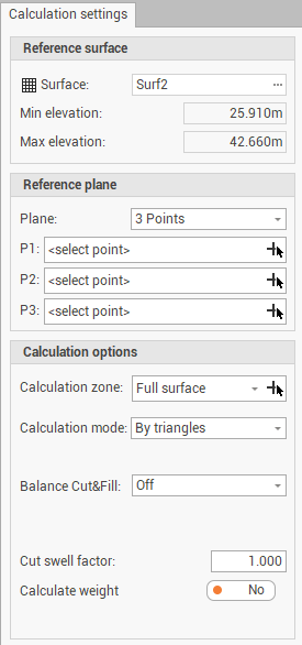
Surface: sets the surface subproject in which to perform the processing.
Min elevation: the minimum elevation of the surface.
Max elevation: the maximum elevation of the surface.
Plane: sets the calculation mode of the plane. The following options are available:
Horizontal: calculates a horizontal plane by selecting a position on the surface. Activates the field P1 where to select the reference point.
3 points: calculate the plane using the indication of 3 positions on the surface. Activates the fields P1, P2 and P3 which define the reference points through which the plane passes
2 Points & 1 Direction: calculate the plane using the indication of 2 positions on the surface, a direction and a slope along the direction. Activates the fields P1 and P2 which define the 2 reference points and the fields First direction and First slope, where it is possible to enter the reference direction and slope of the plane.
1 Point & 2 Directions: calculate the plane using the indication of 1 position on the surface, two directions and two slopes along the 2 directions. Activates the field P1 where to select the reference point. Activates the fields First direction, First slope, Second direction and Second slope where it is possible to enter the reference direction and slope of the plane in the 2 axis.
Calculation zone: if a calculation zone has been configured using the function Add zone, it is possible to select here the surface zone where to perform the volume calculation or selecting the zone from CAD clicking
 .
.Calculation mode: sets the calculation mode, the options available are:
By triangles: the program uses the triangles of the surface.
By regular grid: the program uses a grid with a set step for the calculation.
REB-VB 22.013: The program uses the calculation algorithm for specific calculations of the Earth mass of the Federal Ministry of Transport, Construction and Urban Development Department of Road Construction of Germany.
Grid step: sets the step of the grid if the calculation mode is set to By regular grid.
Balance Cut&Fill: activates the calculation of the volume balance. The program determines the position of the plane in which the cut and fill volumes are equal. To perform the calculation, you can choose the following options:
Off: It does not perform any balance.
By elevation (vertical): Performs the balance while maintaining the slope of the plane and changing the elevation.
By slope (rotation): Balance while maintaining the elevation of the plane and changing the slope. This option is available if the plan was calculated with the 2 Points & 1 Direction.
Cut swell factor: sets the expansion factor of the excavation after the movement.
Calculation weight: enables/disables the calculation of the weight of the handled material.
Weight (t/m3): sets the ratio between a ton and a m3 of material.
Press Calculate to perform the calculation.
After the calculation the Results panel is activated, which reports the results of the processing set.
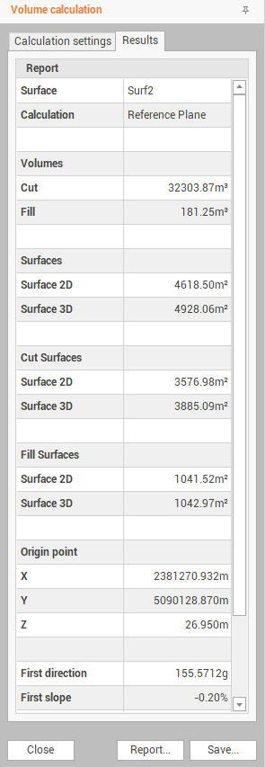
You can perform the following operations from the bottom bar of the panel:
Report: accesses the Report Manager workspace from which the processing report can be printed.
Save: activates a wizard that allows you to:
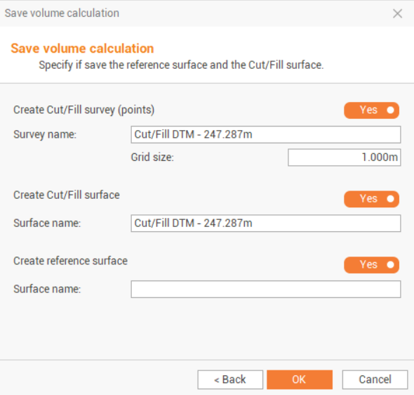
Save volume calculation. It will be recorded in Calculated volumes (see Calculated volumes ).
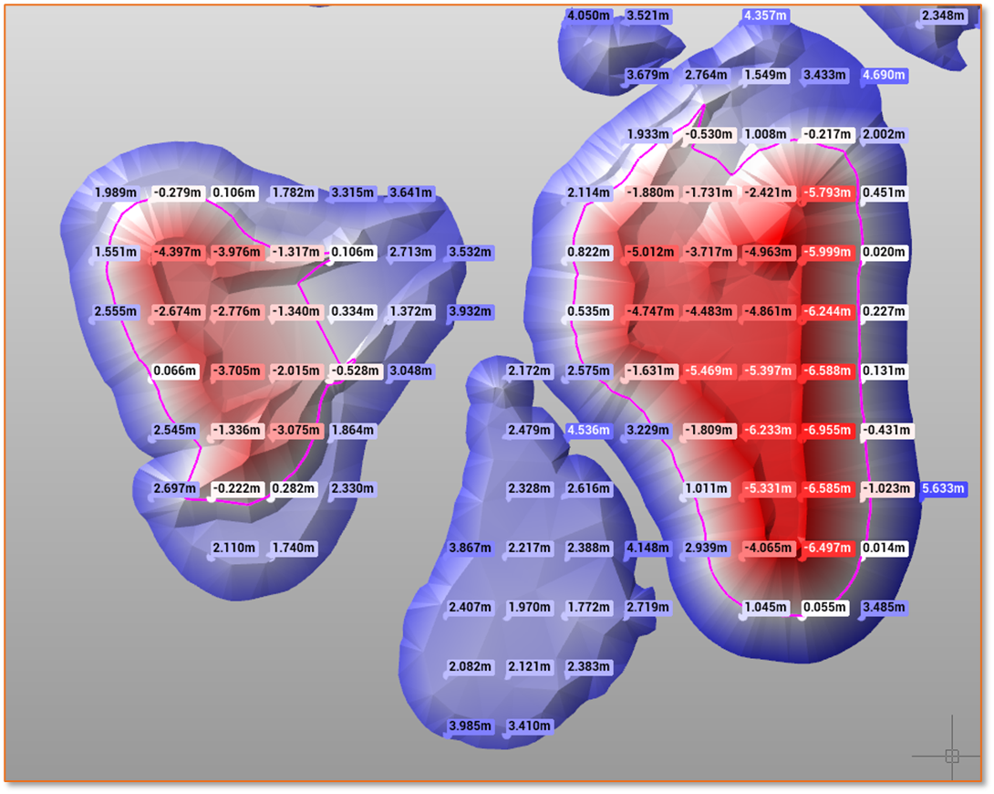
Create Cut/Fill survey (points): allows to create topographic points on the surface on grid with defined size with custom labels reporting existing elevation, design elevation, elevation difference.
Create cut/fill surface: creates a new surface where elevations represent the cut/fill values.
Create reference surface: creates a surface using the set elevation of the reference point.