BIM tools
 |
| 
BIM tools can be used to extract points or polylines from an IFC/BIM model for subsequent operations.
Click Draw.
Click BIM Tools.
Select the function to use:
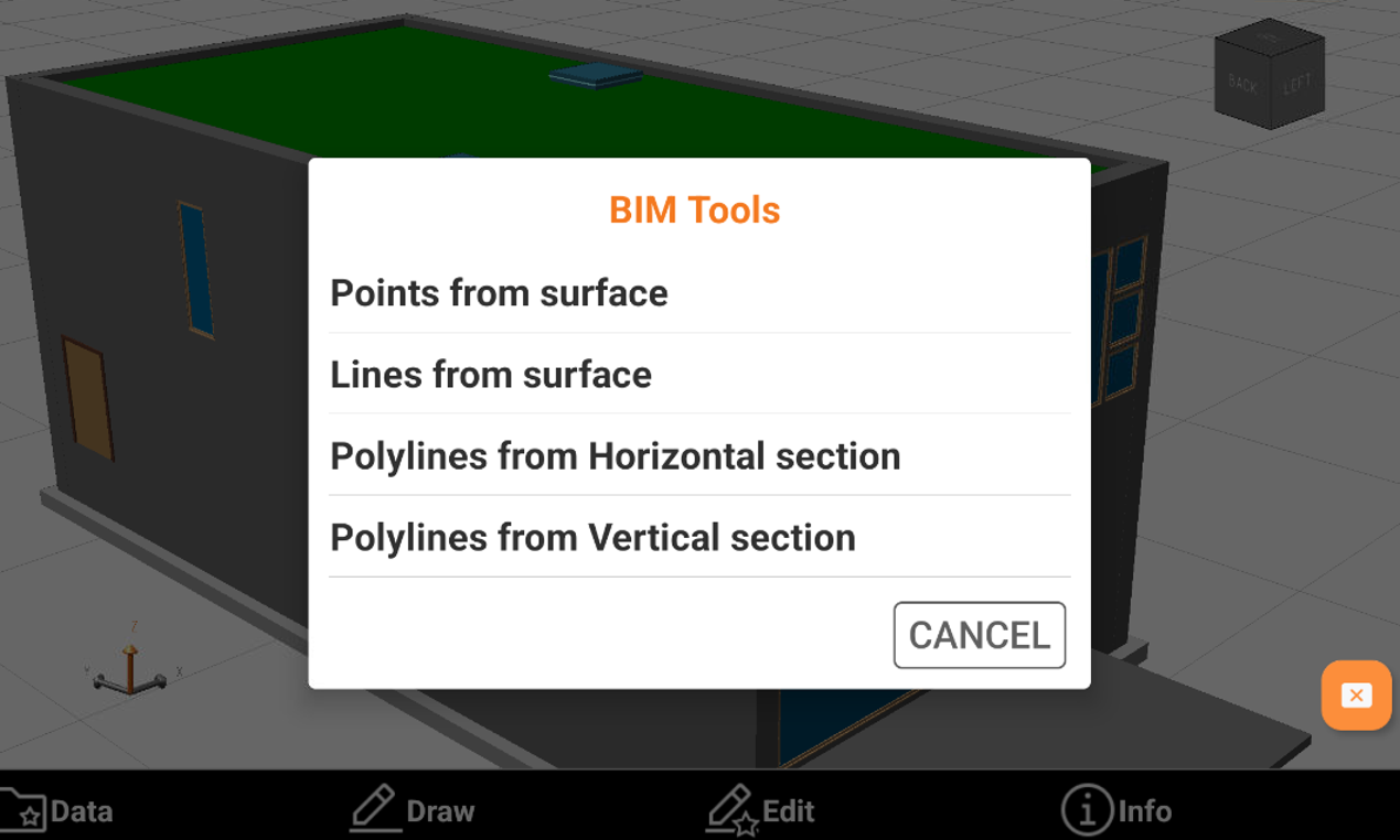
Points from surface: automatically inserts topographic points at the vertices of selected 3D objects.
Lines from surface: automatically inserts topographic points at the edges of selected 3D objects.
Polylines from Horizontal section: extracts the line of a horizontal section from the model. The model is cut using a horizontal plane based on the specified elevation. The command can create section lines as well as points at the intersection of the plane with the IFC elements.
Polylines from Vertical section: extracts the line of a vertical section from the model. The model is cut using a vertical plane based on selected points. The command can create section lines as well as points at the intersection of the plane with the IFC elements.
Points from surface
Points from surface automatically inserts topographic points at the vertices of selected 3D objects.
Click Bim Tools.
Select Points from surface.
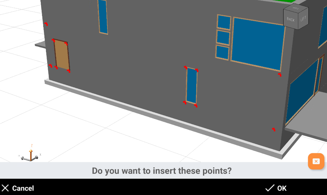
Select the surface on the model and click OK.
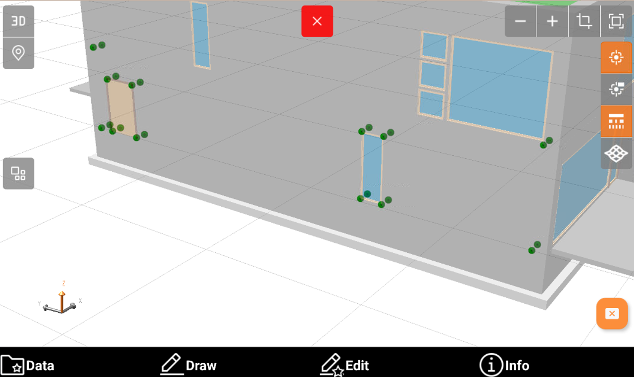
The software shows a preview for the new points. Click OK.
Enter the starting name for the new points and the layer. Click OK to create the points.
Lines from surface
Lines from surface automatically inserts topographic points at the edges of selected 3D objects.
Click Bim Tools.
Select Lines from surface.
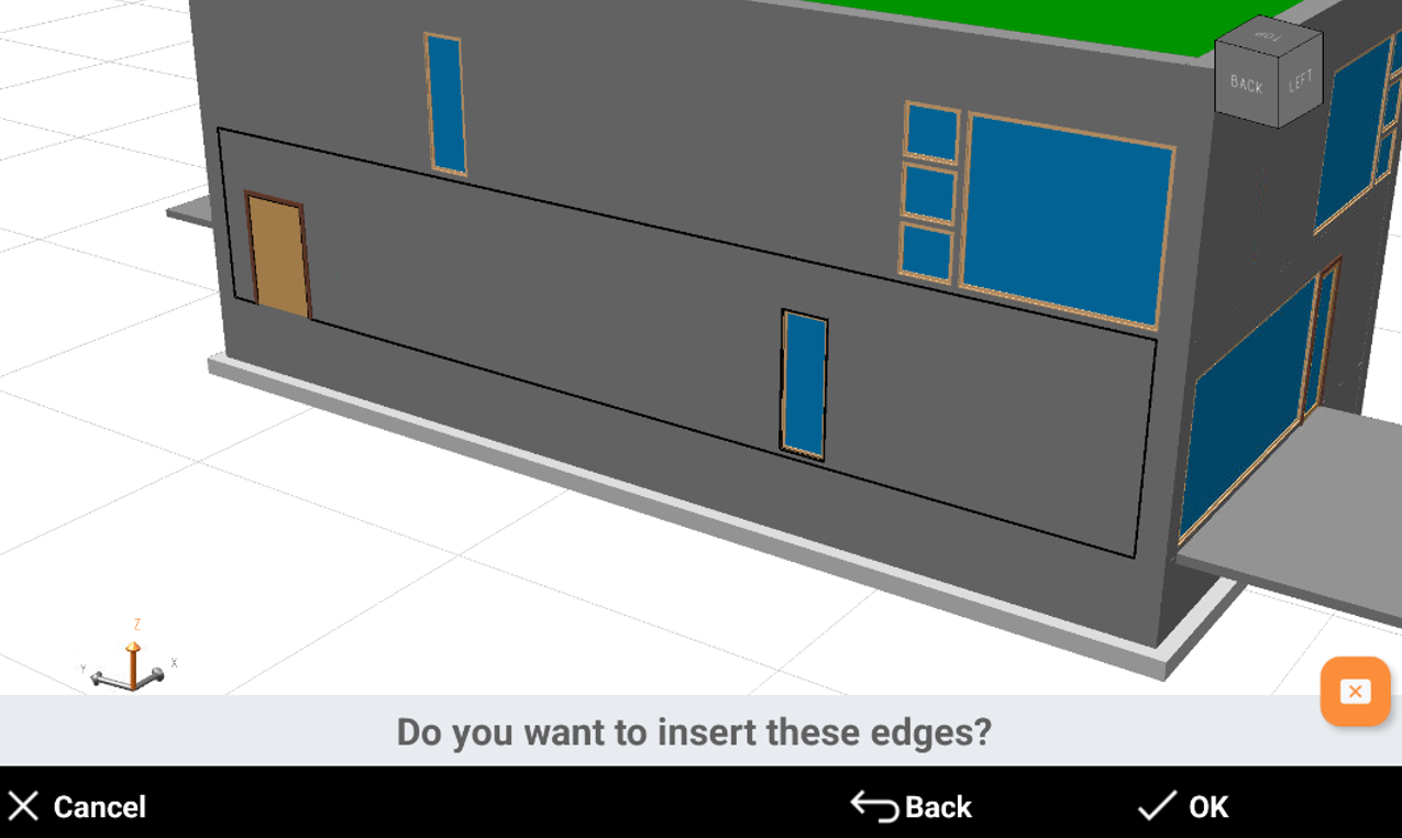
Select the surface on the model and click OK.
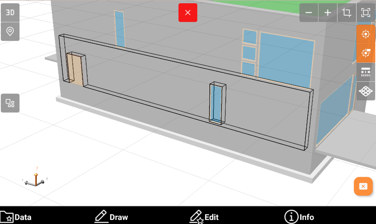
The software shows a preview for the new lines. Click OK.
Enter the layer. Click OK to create the lines.
Polylines from Horizontal section
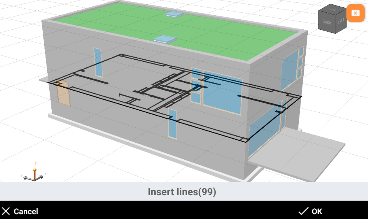
Polylines from Horizontal section extracts the line of a horizontal section from the model.
The model is cut using a horizontal plane based on the specified elevation.
The command can create section lines as well as points at the intersection of the plane with the IFC elements.
Click Bim Tools.
Select Polylines from Horizontal section.
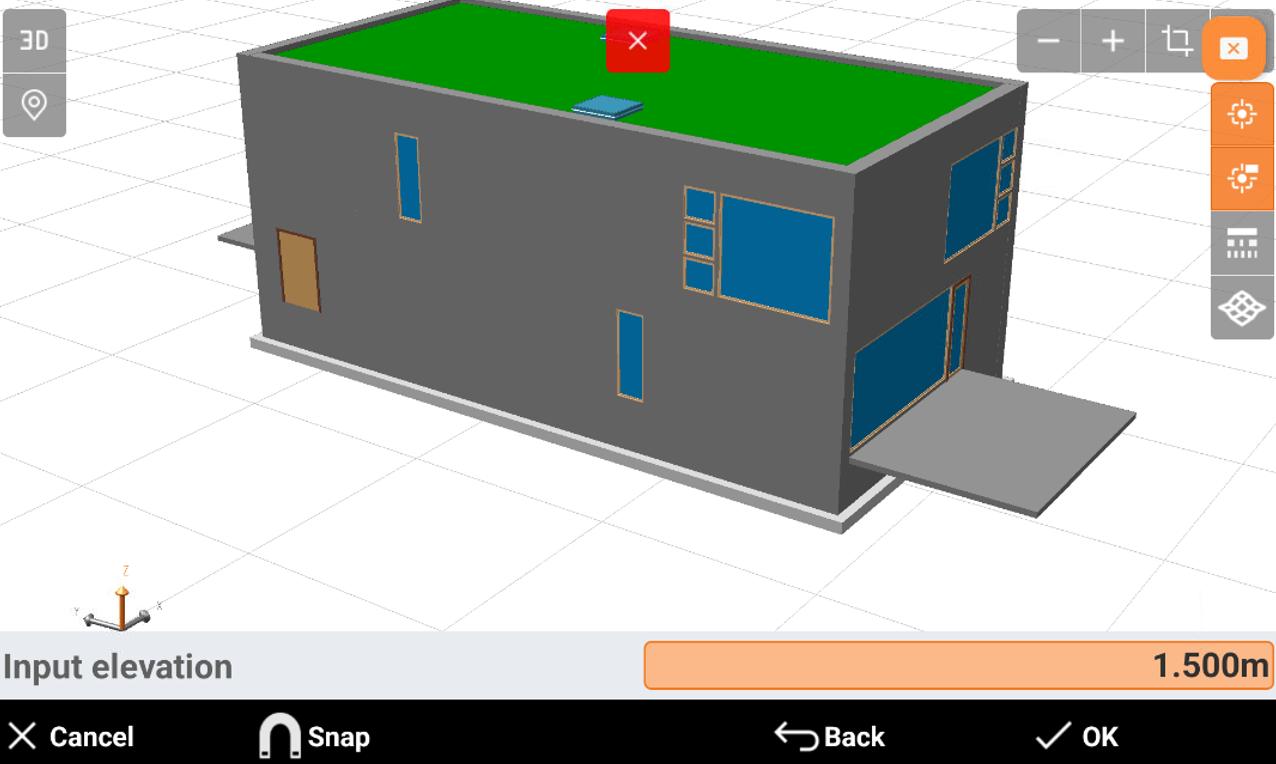
Enter the elevation or click on the model to define the elevation of the cross section.
Select the options:
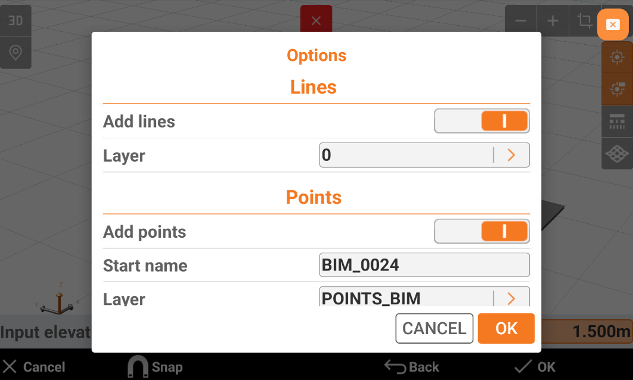
Add lines: enables the creation of lines.
Layer: select the layer where to create the lines.
Add points: enables the creation of points.
Start name: the starting name of the created points.
Layer: select the layer where to create the points.
Click OK.
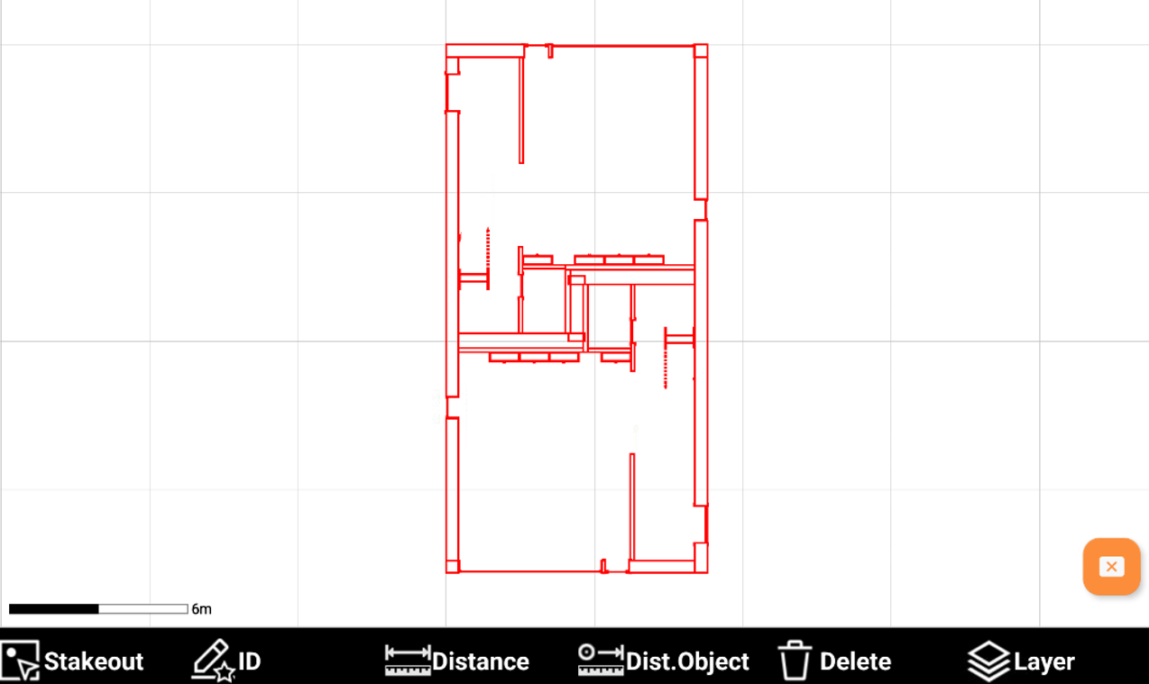
The software shows a preview of the cross section showing the lines and the points, depending on previous options. Click OK to create the points and lines.
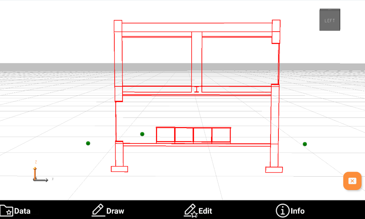
The software creates the horizontal cross section.
Polylines from Vertical section
Polylines from Vertical section extracts the line of a vertical section from the model.
The model is cut using a vertical plane based on the specified direction.
The command can create section lines as well as points at the intersection of the plane with the IFC elements.
Click Bim Tools.
Select Polylines from Vertical section.
Select the first and second points on the model to define the cross section direction.
Select the options:
Add lines: enables the creation of lines.
Layer: select the layer where to create the lines.
Add points: enables the creation of points.
Start name: the starting name of the created points.
Layer: select the layer where to create the points.
Click OK.
The software shows a preview of the cross section showing the lines and the points, depending on previous options. Click OK to create the points and lines.
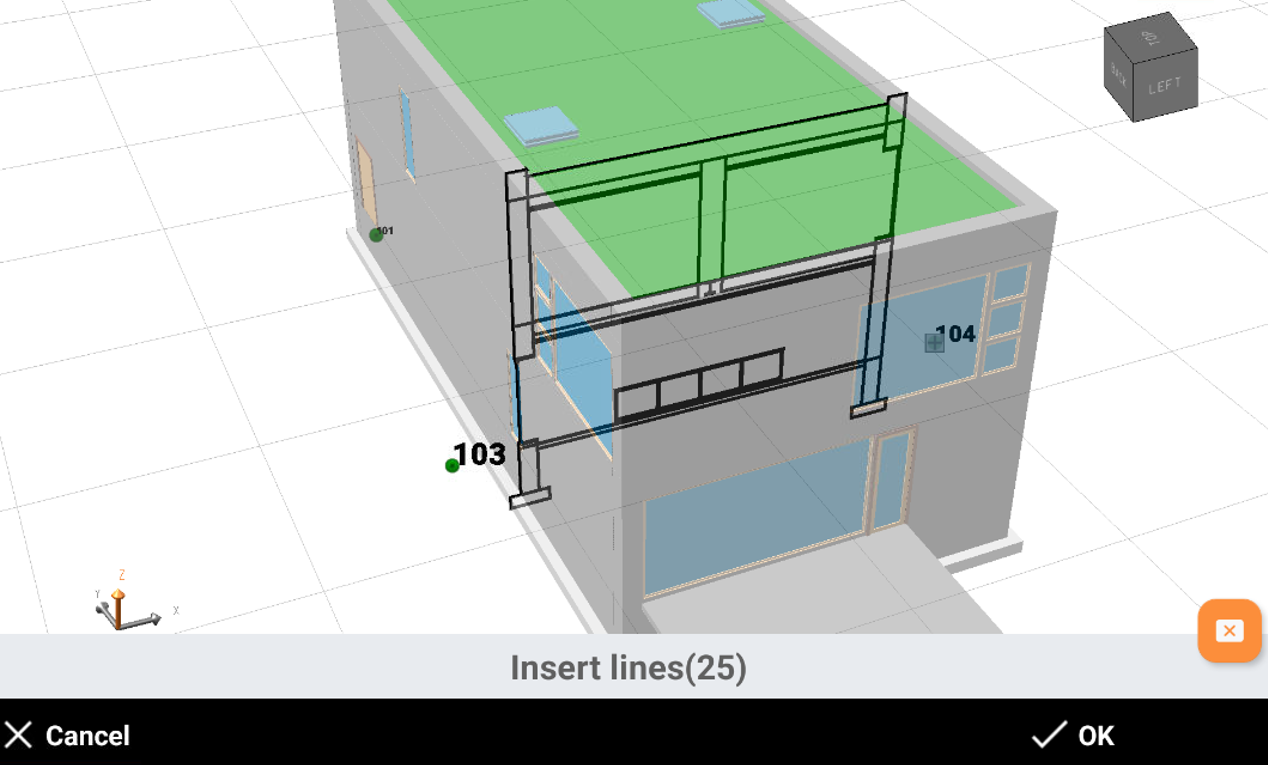
The software creates the vertical cross section.