CAD settings
 |
|  |
| 
The tab allows to set different display parameters of the CAD workspace.
Click Settings.
Click CAD.
Survey tab
Survey tab allows to change the display in CAD of survey entities.
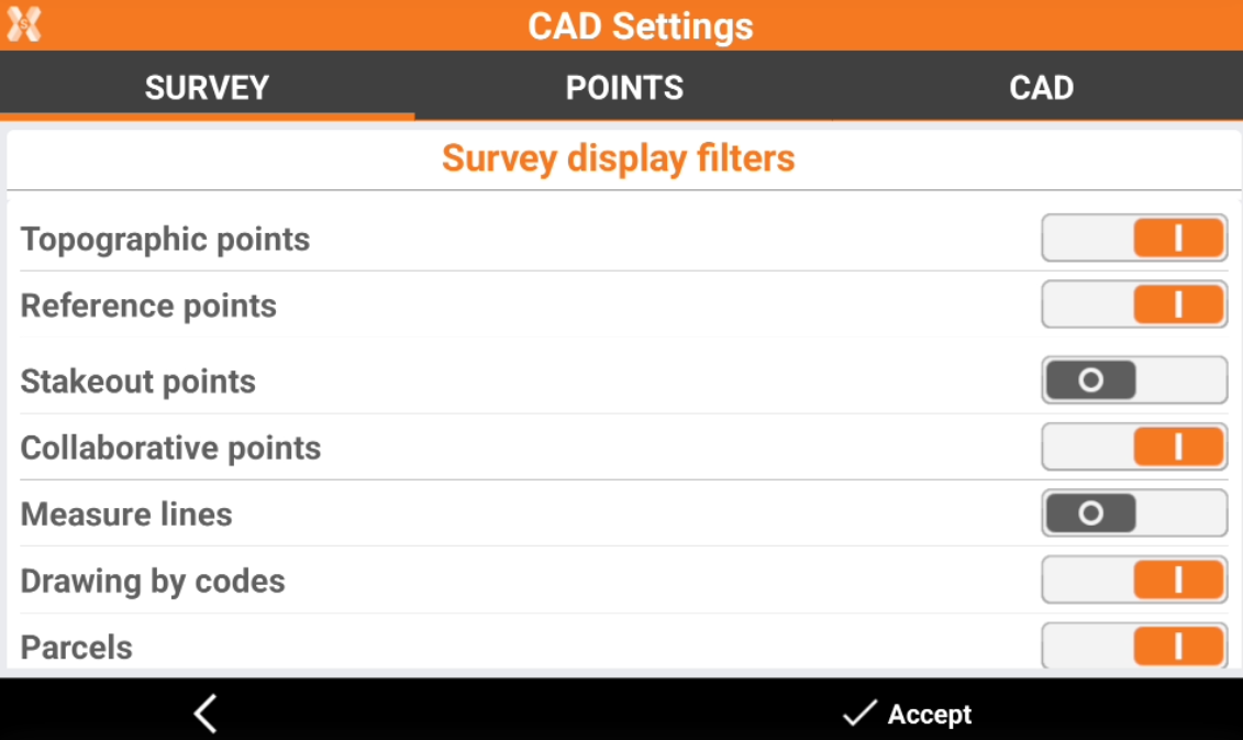
Survey display filters
Topographic points: turns on/off the display of stored points.
Reference points: turns on/off the display of reference points.
Stakeout points: turns on/off the display of stakeout points.
Collaborative points: turns on/off the display of collaborative points shared in a collaborative survey with X-PAD 365.
Measure lines: turns on/off the display of measure lines.
Drawing by codes: turns on/off the display of drawing by codes.
Parcels: turns on/off the display of parcels.
Points tab
Points tab allows to change the visualization in CAD of points and point labels.
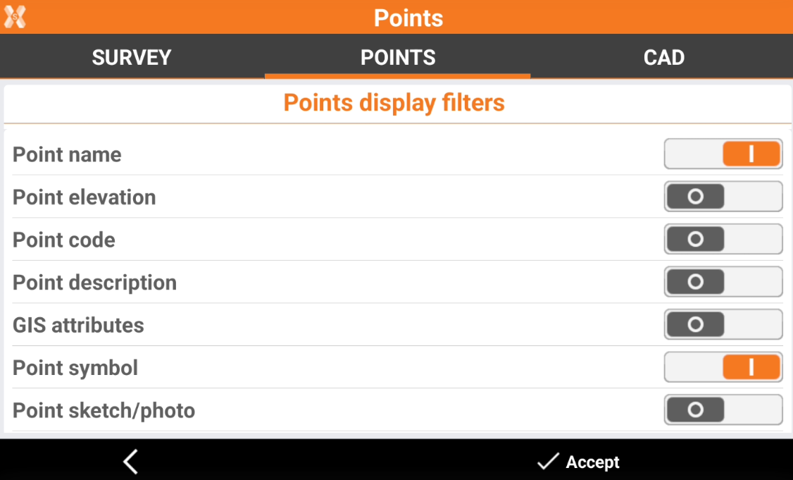
Points display filters
Point name: turns on/off the display of the point name.
Point elevation: turns on/off the display of the point elevation.
Point code: turns on/off the display of the point code.
Point description: turns on/off the display of the point description.
GIS attributes: turn on/off the display of GIS attributes associated with the point.
Point symbol: turns on/off the display of the point symbol.
Point sketch/photo: turns on/off the display of an icon to indicate if the point has a photo or a sketch associated.
Point label color from Layer: if this option is enabled, the point label color matches the color of the corresponding layer.
Points symbol and label size
Point size: allows to set the size used to display the text of labels.
Auto size labels in 3D: turns on/off automatic text size management when 3D display is active. If the option is active, the size of the text changes depending on the distance. The closest text is displayed with a larger size than text further away.
CAD tab
CAD tab allows to change the display settings of the CAD.
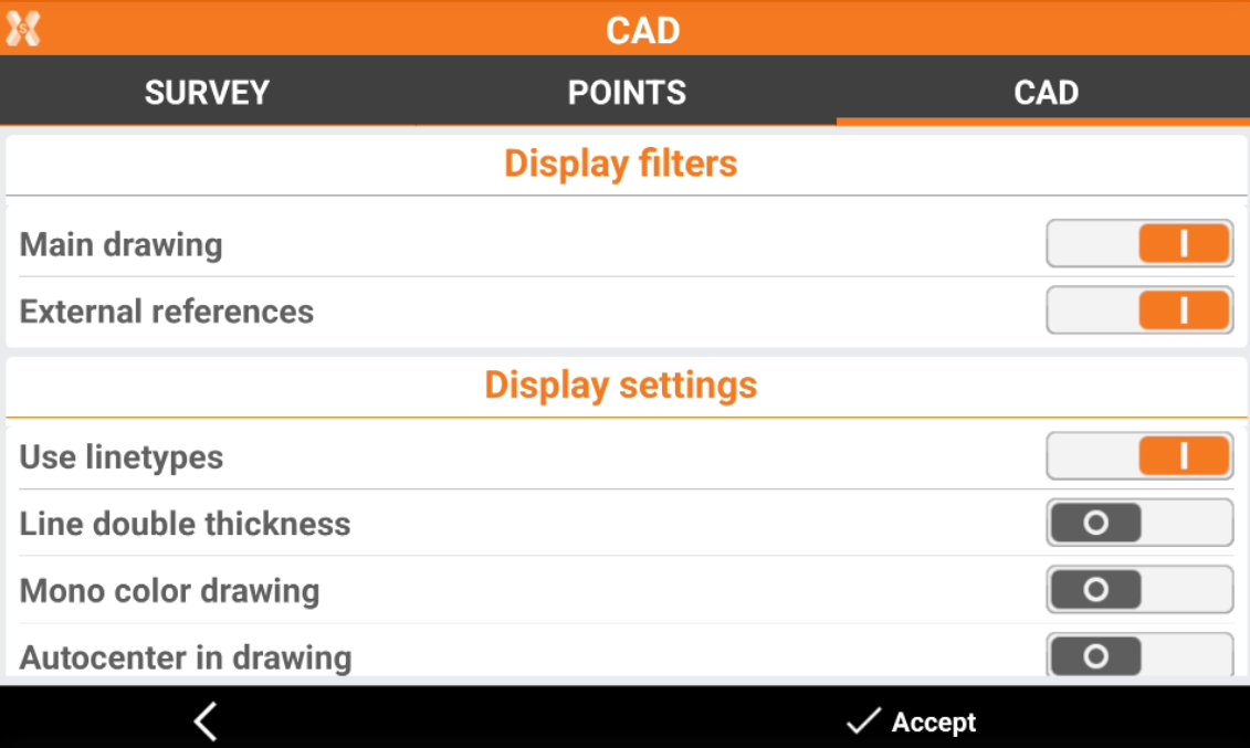
Display filters
Main drawing: turns on/off the display of drawing elements.
External references: turns on/off the display of elements stored in the external reference.
Display settings
Use linetypes: turns on/off the display of line types associated with the drawing elements.
Line double thickness: turns on/off the display of drawing elements with a doubled thickness.
Mono color drawing: turns on/off the display of colours for drawing element.
Autocenter in drawing: turns on/off the automatic centring of the drawing. During drawing operations, each time a CAD location is set, it is shown in the centre of the graphical window.
Curve approximation: allows to define how curves are visualized. On controller with low-performance a setting to define a lower curve approximation may increase the CAD performance with drawing with lot of curves and arcs.
Grid: turns on/off the display of the grid in the CAD window.
Grid step: sets the steps of the grid.
Font anti-aliasing: turns on/off the anti-aliasing for the texts.
Background
CAD: allows to select the default background for CAD.
None: the CAD uses the standard white backgound color.
Map: the CAD uses a light brown background color.
Custom: allows to choose a custom background color for CAD.
Survey/Stakeout: allows to select the default background for survey and stakeout functions.
None: the survey and stakeout functions use the standard white background color.
Map: the survey and stakeout functions use uses a light brown background color.
Custom: allows to choose a custom background color for survey and stakeout functions.
Bathymetry: allows to select the default background for bathimetric surveys.
None: the bathimetric survey uses the standard white backgound color.
Map: the bathimetric survey uses a light brown background color.
Sea: the bathimetric survey uses a blue background color.
Custom: allows to choose a custom background color for bathimetric surveys.