GNSS settings
 |
|  |
| 
The GNSS tab allows:
Setting several parameters controlling the acquisition of the positions of the GPS receiver.
Setting the functioning modes.
Click Settings.
Click GNSS.
GNSS tab
The GNSS tab allows to edit the accuracy setting for the GNSS receivers and change some general settings when working with GNSS.
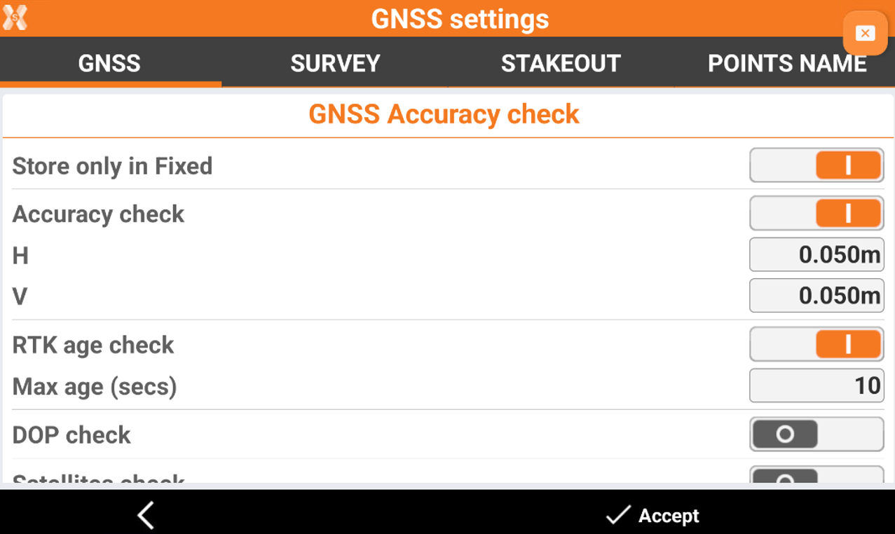
GNSS Accuracy check
Store only in Fixed: the epochs recording is done only if the receiver is in fixed position.
Accuracy check: activates accuracy check. GPS epoch is accepted if the current precision satisfies the preset precision conditions for H and V components.
H: maximum horizontal precision for an acceptable GPS epoch.
V: maximum vertical precision (elevation) for an acceptable GPS epoch.
RTK age check: enables control of receiving corrections. When activated, corrections must be received within the time set to store the point.
Max age (secs): sets the maximum time that the new RTK fix needs to be received.
DOP check: activates the check on DOP value. The GPS epoch is accepted if the DOP value is lower than the preset one. Max DOP Maximum DOP value to make acceptable the GPS epoch.
Satellites check: activates the number of satellites checked. The GPS epoch is accepted if the number of tracked satellites is more than the minimum value preset.
Tilt check: when working with a GNSS receiver with IMU, if the antenna inclination exceeds the allowed maximum tilt entered, the position cannot be accepted or stored.
Max tilt (°): defines the maximum allowed tilt angle when working with a GNSS receiver with IMU.
Min Satellites: minimum number of satellites required for an acceptable GPS epoch.
Sensors mode: it is possible to set the use of different types of sensors in surveying and stakeout phases:
None: no sensor.
E-Bubble: activates the use of an electronic bubble of the controller. The GPS epoch is accepted if the electronic bubble is inside the tolerance range. This can be activated with any GNSS receiver since it will use sensors within the controller.
E-bubble (GNSS receiver): available for receivers with IMU. Activates the use of an electronic bubble of the GPS receiver (if present). The GPS epoch is accepted if the electronic bubble is inside the tolerance range.
Tilted pole (GNSS receiver): available for receivers with IMU. Activates the use of tilt and compass sensors of the GPS receiver (if present). Sensors allow to calculate the position of the point even if the pole is not vertical. To turn off the e-bubble temporarily while surveying, tap once into the survey panel and select Deactivate. The position is stored without any check.
Max error (2m pole): maximum error acceptable outside the bubble considering a 2 meter pole.
Localization area check: activates the GPS localisation zone check. If a coordinate system defined by a localisation on more than two points is set, the software verifies if the receiver position is inside the localisation zone. If the current position is outside of the localisation zone, an icon is displayed on the coordinates panel in survey and stakeout windows.
Miscellaneous
GNSS position symbol: select the symbol that represents the position of the GNSS receiver during surveying.
GNSS symbol 3D: enables the display of a 3D symbol for the instrument, when the 3D view is active in the survey and stakeout graphics window.
Configure always GNSS receiver: enables the complete reconfiguration of the receiver with the current profile at each connection with the controller.
Photos store mode: decide which pictures to store in case pictures are taken during the survey.
All photos: all photos are stored.
Only low res. photo: only low resolution photos are stored.
Only high res. photo: only high resolution photos are stored.
Only geo tagged photo: only geo tagged photos are stored.
Survey tab
The tab allows to set the main functioning parameters for the different GPS survey modes.
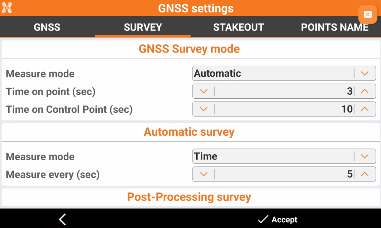
GNSS Survey mode
Measure mode:
Automatic: measurement ends automatically after the preset number of seconds.
Time on point (sec): seconds of acquisition of the position of the point. For every second, a number of epochs equal to the frequency is saved in the GPS profile. For example: 1 Hz frequency = One position (epoch) per second, 5 Hz = Five positions (epochs) per second. To decrease the occupation time to one single epoch click the corresponding icon to reduce the occupation time to shorter than one second.
Time on Control Point (sec): sets the seconds of acquisition of the position for a point of type Master point.
Automatic survey
Measure mode: mode to use for the automatic points survey:
Time: position is acquired at intervals of time.
Distance 2D: position is acquired at intervals of horizontal distance.
Distance 3D: position is acquired at intervals of three-dimensional distance.
Distance 2D Plus: position is acquired at intervals of horizontal distance and height difference according to settings.
Stop & Go: position is acquired according to Stop & Go mode. When the antenna remains static, the software begins to acquire the position.
Measure every (sec): In case of Time mode: Defines the interval of time between the automatic acquisition of positions.
Distance 2D: in case of Distance 2D mode. Defines the interval of horizontal distance that must be between the position to acquire and the position previously acquired.
Distance 3D: in case of Distance 3D mode. Defines the interval of three-dimensional distance that must be between the position to acquire and the position previously acquired.
Distance 2D Plus: in case of Distance 2D Plus mode. Defines the interval of horizontal distance and the height difference that must be between the position to acquire and the position previously acquired. The point is acquired when one of the values is exceeded.
Stop time (sec): in case of Stop & Go mode. Defines the time to stay on the point to allow the acquisition of position.
Max antenna movement: on case of Stop & Go mode. Represents the maximum movement allowed to consider a static antenna. When the software identifies that the antenna remains in static position with a movement lower than the maximum value, the acquisition of the position begins for the defined time.
Post-processing survey
Measure mode:
Automatic: measurement ends automatically after the preset number of seconds.
Survey codes
Numeric codes: activates a preferential use of numeric codes concerning survey codes. The virtual keyboard appearing is the numeric one.
Measure after Quick Code: when activated, measurements start immediately automatically after the selection of the Quick Code.
Add new codes to library: when activated, a code used during the surveying that is not store in the library yet, is added automatically.
GIS line attributes:
For all points: GIS attributes are required for each point of the line.
To first point: GIS attributes are required for the first point of the line.
To last point: GIS attributes are required for the last point of the line.
Average coordinates
Average coords: activates the calculation of the average point coordinates when measured multiple times.
Max H/V: tolerance for distances and elevations If a measurement differs from the average value more than the defined tolerance, it is highlighted in the list of measurements.
Miscellaneous
Survey display mode: sets the default display mode of the survey graphics window performed with GNSS.
2D (walk direction): displays items of drawing and surveying in 2D oriented mode according to the direction of the antenna.
2D (north): displays items of drawing and surveying in 2D oriented mode according to North.
3D (walk direction): displays items of drawing and surveying in 3D oriented mode according to the direction of the rover.
Map: displays a reference map in surveying operation.
Stakeout tab
The tab allow to set the functioning and control parameters for the GPS stakeout.
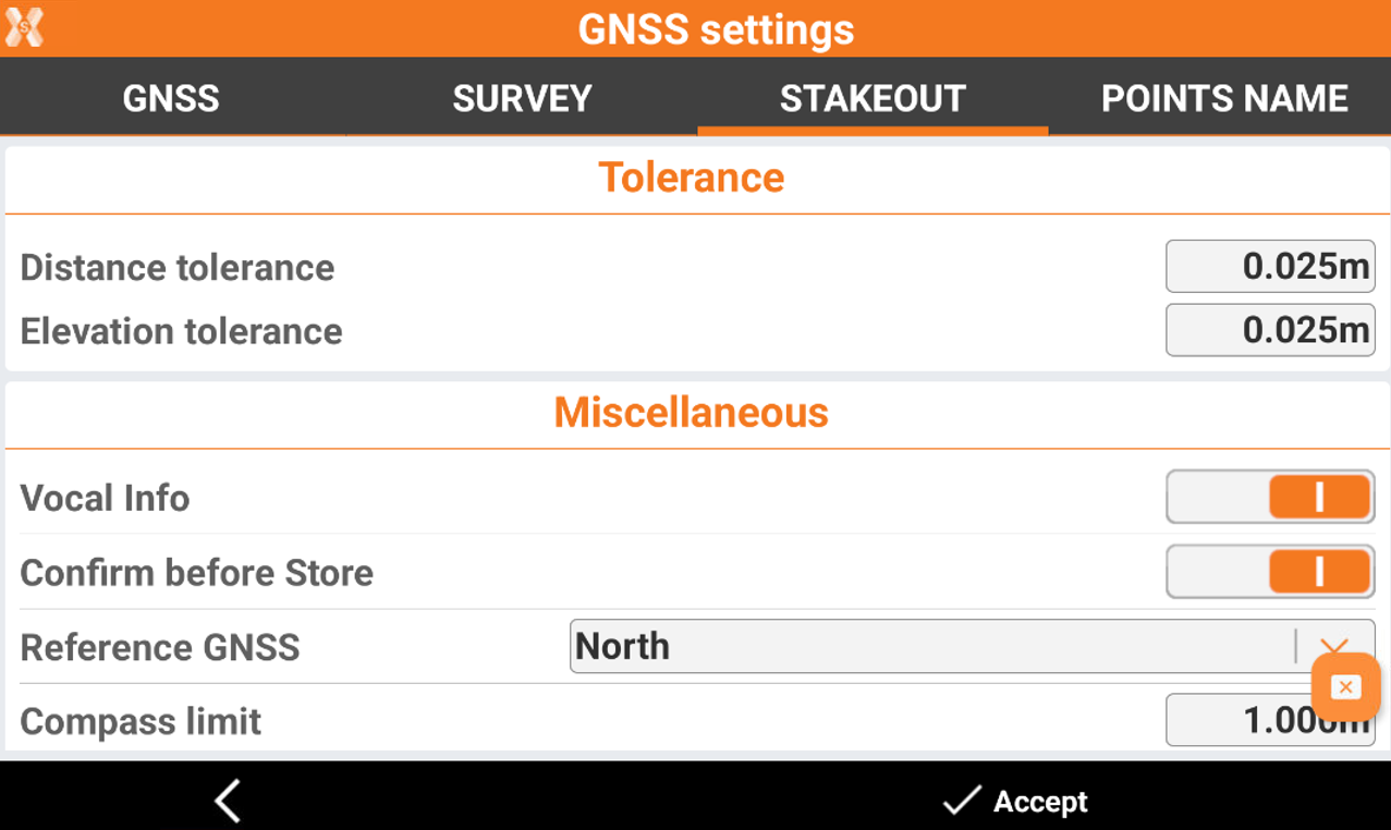
Tolerance
Distance tolerance: maximum horizontal distance between current position and stakeout position. If the distance between current position and position to reach is lower than or equal to the tolerance, the software reports the reaching of stakeout position.
Elevation tolerance: maximum acceptable difference between current elevation and stakeout elevation If the elevation difference is lower than or equal to the tolerance, the software reports the reaching of the position in elevation.
Miscellaneous
Vocal Info: activates the vocal information during the stakeout operations.
Confirm before Store: allows checking the stakeout position before proceeding to saving the new point on position to stakeout. When disabled, the stakeout point is saved without any further request.
Reference GNSS: defines the reference to which the information to reach the stakeout position with GPS is provided. References can be:
North: information is provided referring to North. Turn the controller toward North and follow indications.
Sun: information is provided referring to the sun. Turn the controller toward the sun and follow indications.
Point: information is provided referring to a reference point. Turn the controller toward the point and follow indications.
Previous point: information is provided referring to the previous stakeout point. Turn the controller toward the point and follow indications.
Reference line: information is provided referring to a reference line.
Compass limit: distance determining the automatic change of visualization of the stakeout information. If the distance of the receiver from the point to stakeout is more than the preset value, an arrow appears indicating the direction. If the distance of the receiver from the point to stakeout is lower than the preset value, a stakeout sketch appears with the reference to North, to the sun or to a point.
Stakeout display mode: sets the default display mode of the stakeout graphics window performed with GNSS.
2D (walk direction): displays items of drawing and staking out in 2D oriented mode according to the direction of the antenna.
2D (north): displays items of drawing and staking out in 2D oriented mode according to North.
3D (walk direction): displays items of drawing and staking out in 3D oriented mode according to the direction of the rover.
Map: displays a reference map in staking out operation.
Point name tab
The window allows the customisation of point names according to the type of point. If the point name is composed of letters and numbers, the program only increases the numerical part during operations.
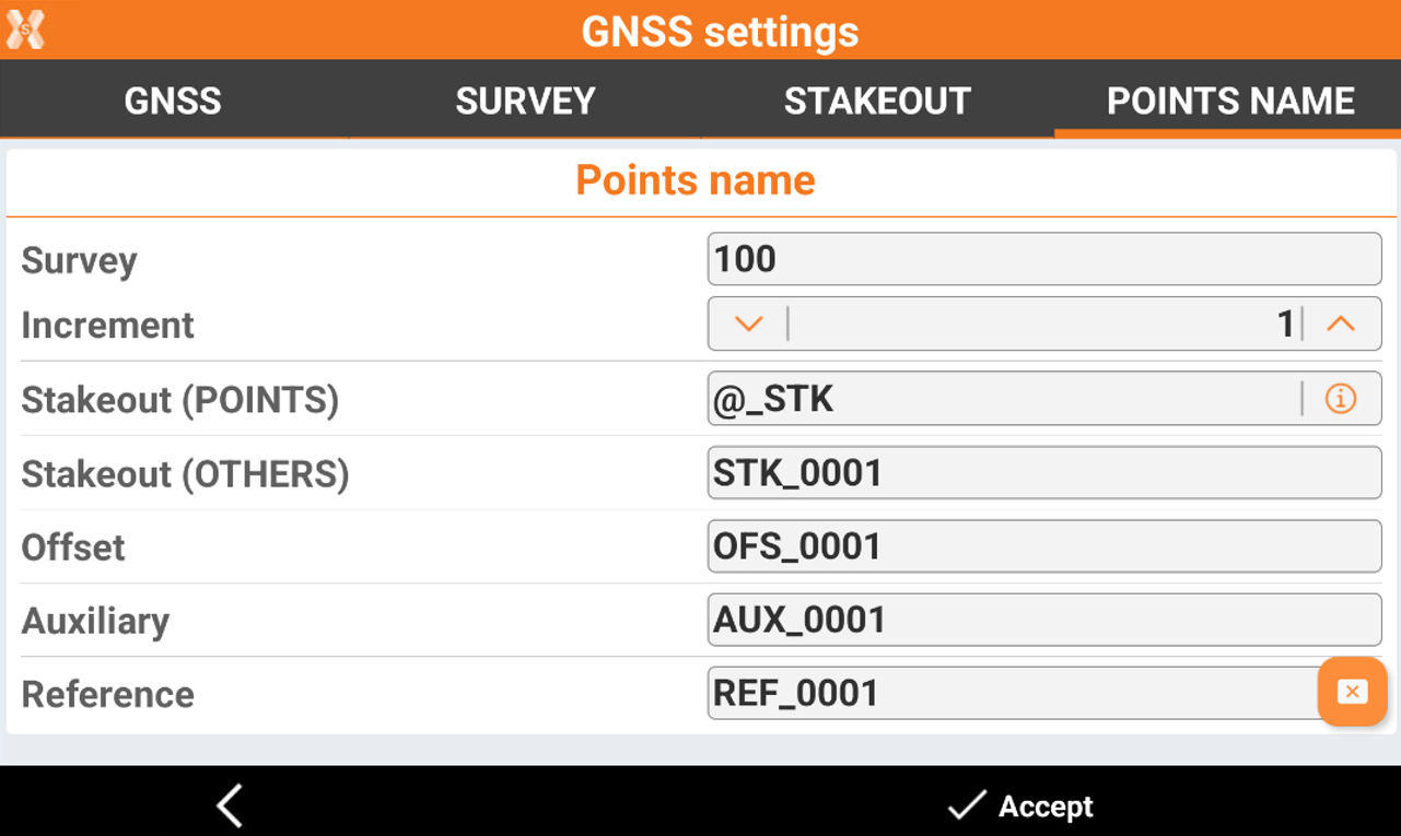
Survey: the starting name for surveying points.
Increment: the increase of the numerical part of the name.
Stakeout (points): the name of stakeout points. The symbol @ if used in the field will be automatically replaced by the name of the staked point. If @ is not entered, then the name of the stored point will not include the name of the original staked point.
Stakeout (others): the name of other stakeout elements.
Offset: the name of offset points.
Auxiliary: the name of auxiliary points.
Reference: the name of reference points.