Layout
 |
| 
Layout function draws consecutive elements setting distances and angles from a starting point. The starting point can be a topographic point or any other position.
Click Draw.
Click Layout.
Select the items to insert.
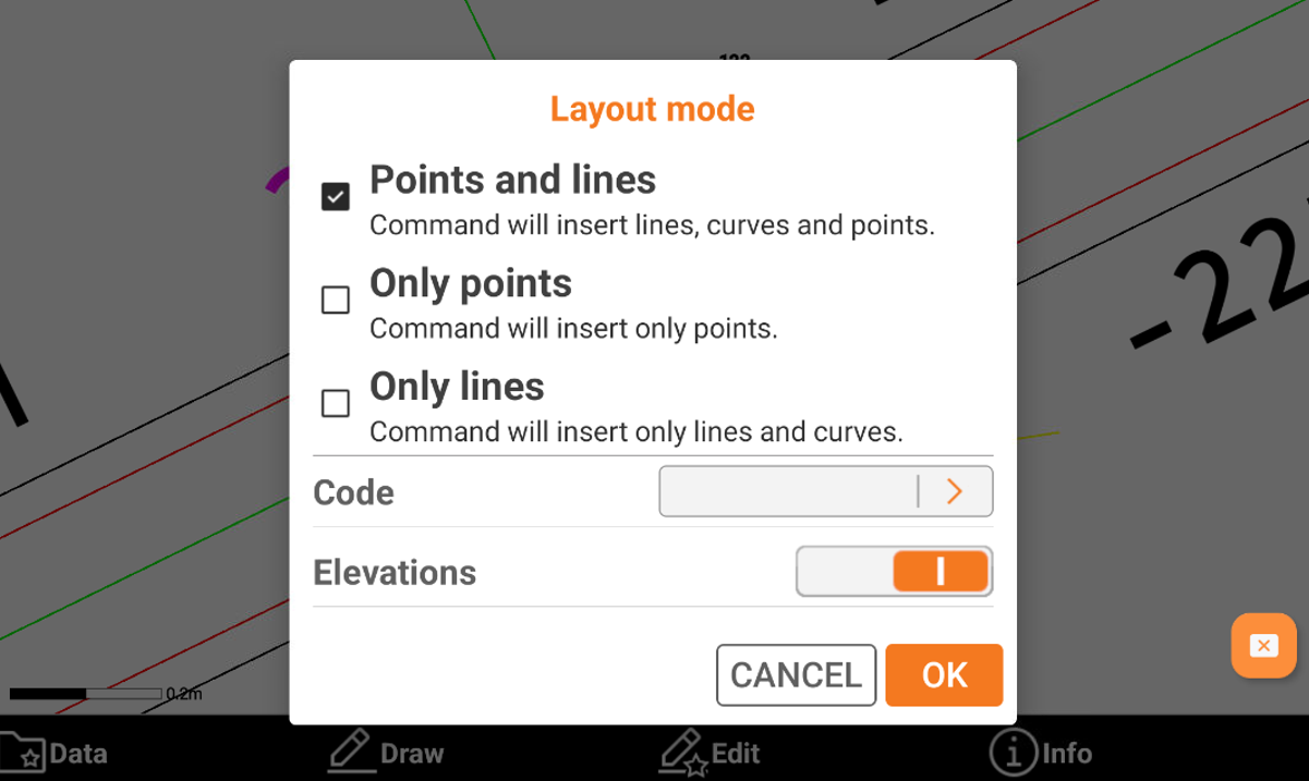
Points and lines: enables the drawing of lines, arcs, and points.
Only points: enables the creation of points only.
Only lines: Enables the draw of lines only.
Code: assigns the code for the topographic points created with layout function.
Elevations: enables the insertion of the elevation for created items. When disabled, the program assigns the elevation start point to the items that are created.
Click OK to enter in the drawing mode.
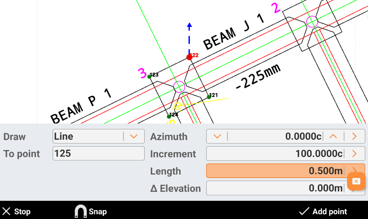
Draw: chooses the drawing element to create and calculate the second point. Use a line or an arc.
To point: sets the insertion point in one of the following ways:
Select the point in the CAD window. Click on a point in CAD to start drawing from selected position.
Click in the box to insert the point name.
Click
 to select the point from the list of topographic points or from the list of reference points. The starting point can be defined every time again after drawing an element.
Azimuth: sets the azimuth. Enter the value in one of the following ways:
Type in the value in the box.
Press Up and Down to increase or decrease the value based on the increment value set in Increment field.
Click
 and select By two points to set the azimuth value based on angle between the two selected points.
Increment: sets the value the software adds or subtracts in the azimuth input, when using Up/Down.
Length: sets the distance between the two points. Click
and select By two points to set the distance value based on distance between the two selected points. Angle: sets the angular development value of the arc. Click
to open the Curve calculator where to calculate the angle based on etnered Radius, Length and Chord.Radius: sets the arc radius value and direction using
 and
and  .
.Elevation: sets the value of the elevation. Enter the value in one of the following ways:
Type in the value in the box.
Click
and select the elevation input mode. Select Absolute elevation to enter the absolute elevation of the new point. Select Delta elevation to enter the different elevation between the points. Select Slope to define the point elevation from the entered slope between the two points.
Draw a layout step by step
In this example we create a draw similar to this layout.
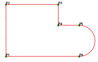
Line P1 - P2
Measure or enter the coordinates of point P1.
Set Draw: Line.
Set Point: P1.
Set Distance: 5 m.
Set Azimuth: 0 c.
Click Add point.
Line P2 - P3
Set Draw: Line.
Set Point: P2.
Set Distance: 8 m.
Set Azimuth: 100 c.
Click Add point.
Line P3 - P4
Set Draw: Line.
Set Point: P3.
Set Distance: 2 m.
Set Azimuth: 200 c.
Click Add point.
Line P4 – P5
Set Draw: Line.
Set Point: P4.
Set Distance: 2 m.
Set Azimuth: 100 c.
Click Add point.
Arc P5 – P6
Set Draw: Arc.
Set Point: P5.
Set Azimuth: 100 c.
Set Angle: 200 c.
Set Radius: 1.5 m.
Click Close to draw the line P5 – P1