Scan plane/surface
 + ROBOTIC |
  + ROBOTIC
The function Scan plane/surface allows to use the motorized total station to perform an automatic measurement of a plane or a generic surface.
Scan plane
Scan plane uses the motorized total station to perform an automatic measurement of a plane (horizontal, vertical or sloped) surface; the reference plane can be also a surface of an IFC model.
It is possible to define the area to scan (rectangular or polygonal), the grid size and the software will drive the Total station to measure each single point of the grid.
The result of the scan is a colorized grid of points and a 3D surface in which areas out of tolerance are immediately visible; the tolerance can be changed interactively and a new colorized map is generated.
To identify the areas out of tolerance in the physical plane, just select a point on the screen and TPS will rotate toward the selected point.
Points and surface can be exported (in 3D or plane 2D coordinates) to be used in different ways.
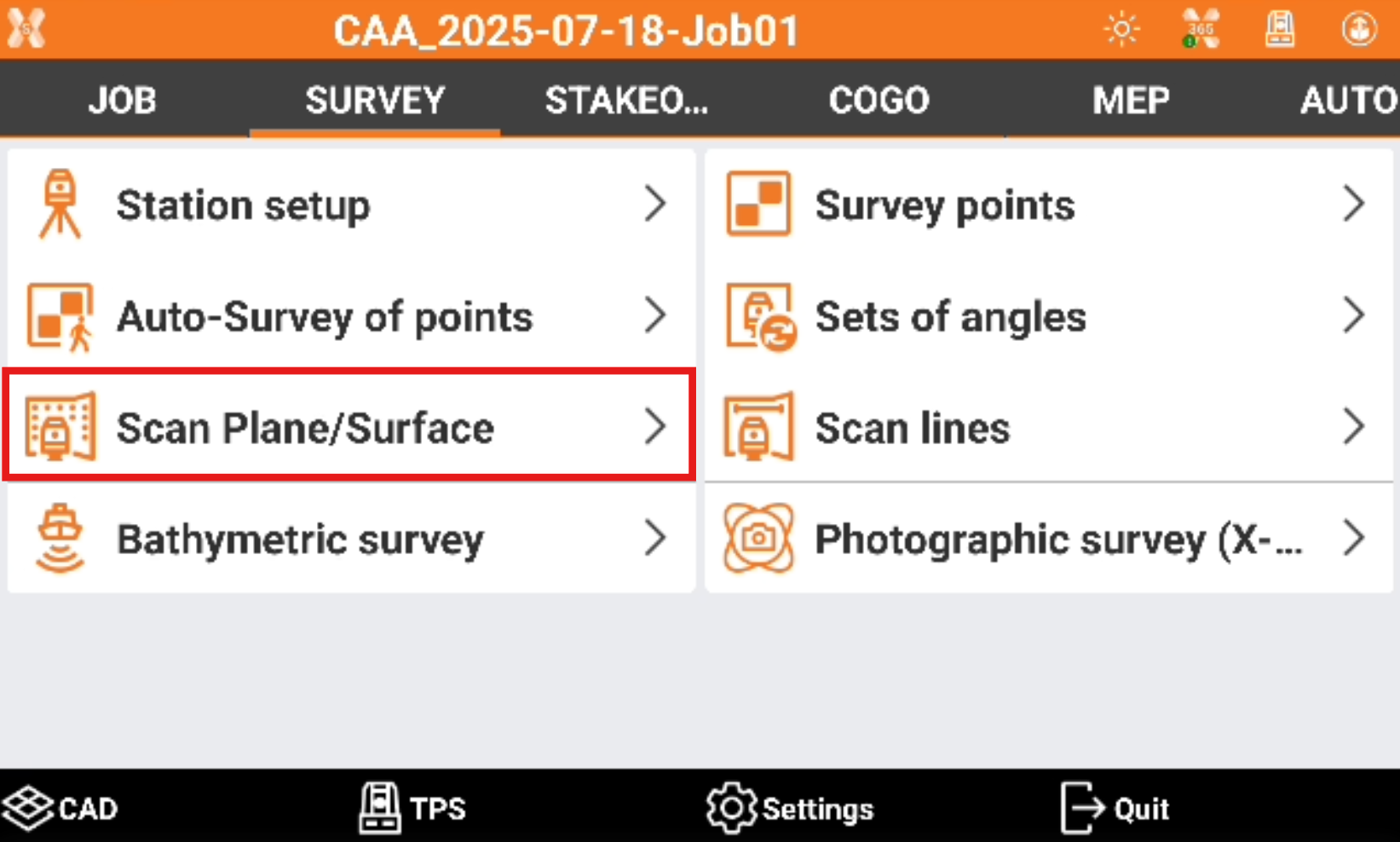
Click Survey.
Click Scan plane/surface.
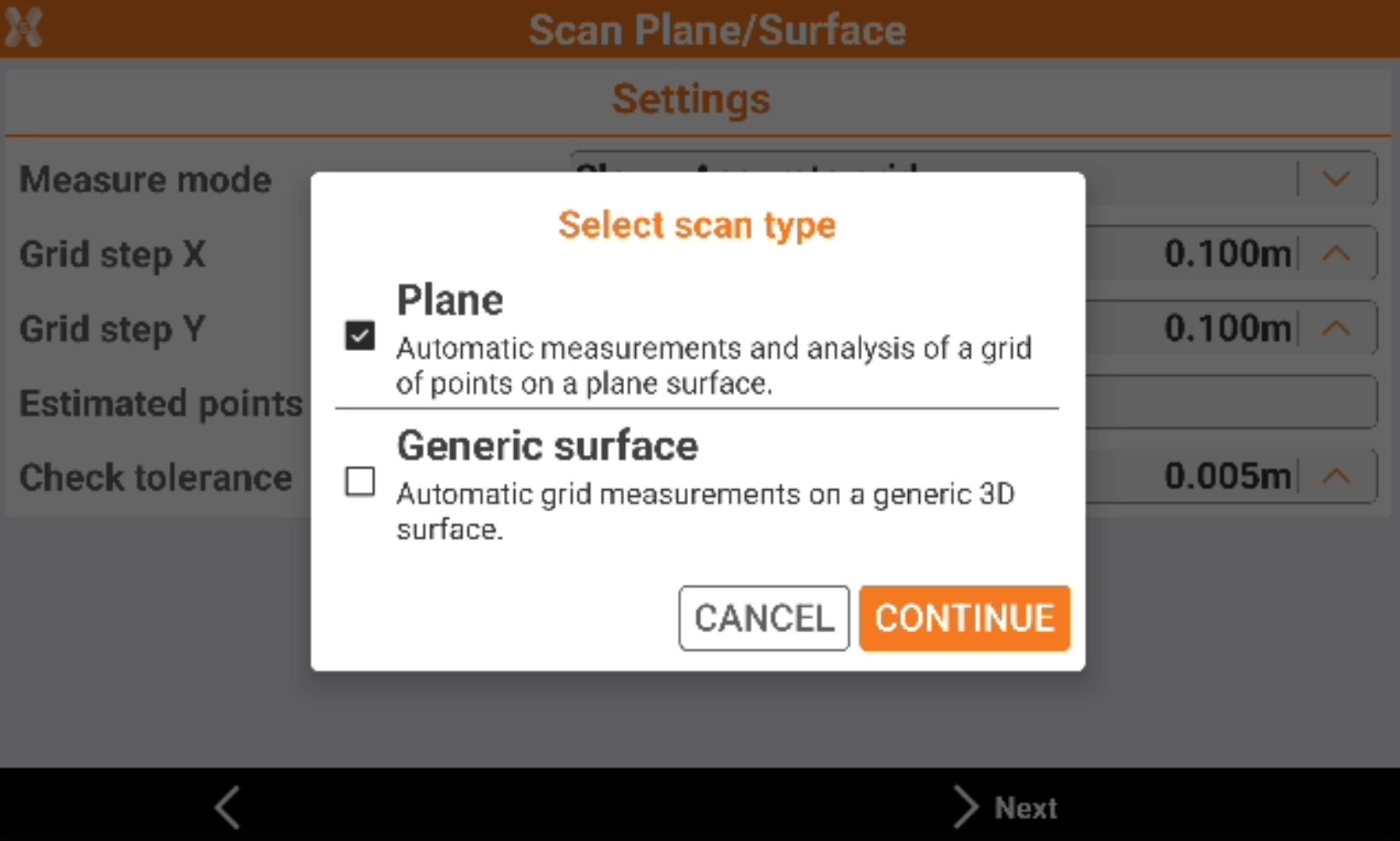
Select Plane.
Select the reference plane.
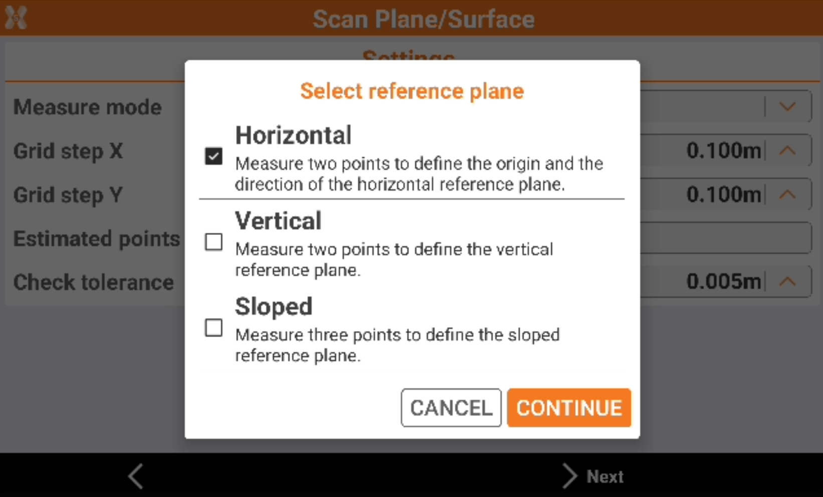
Horizontal: the reference plane is horizontal. The plane is defined measuring the origin and the direction of the horizontal reference plane.
Vertical: the reference plane is vertical. Two points are measured to define the plane.
Sloped: the reference plane is sloped. Three points are measured to define the plane.
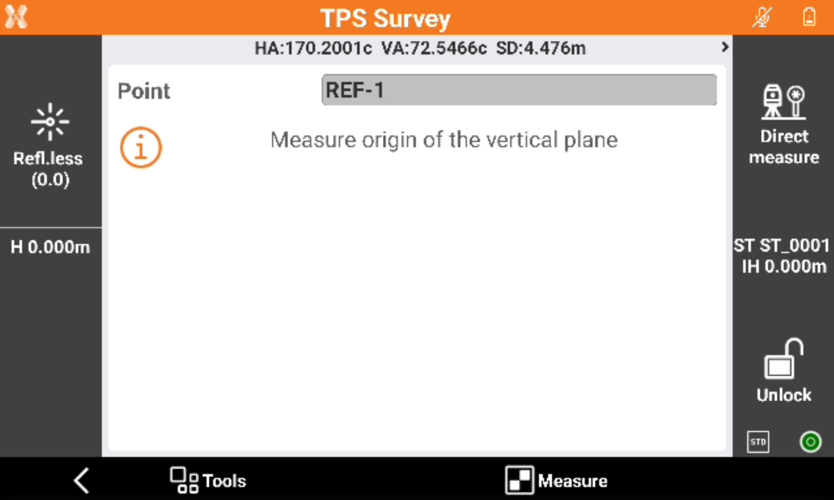
Click Next to define the plane measuring the required reference point.
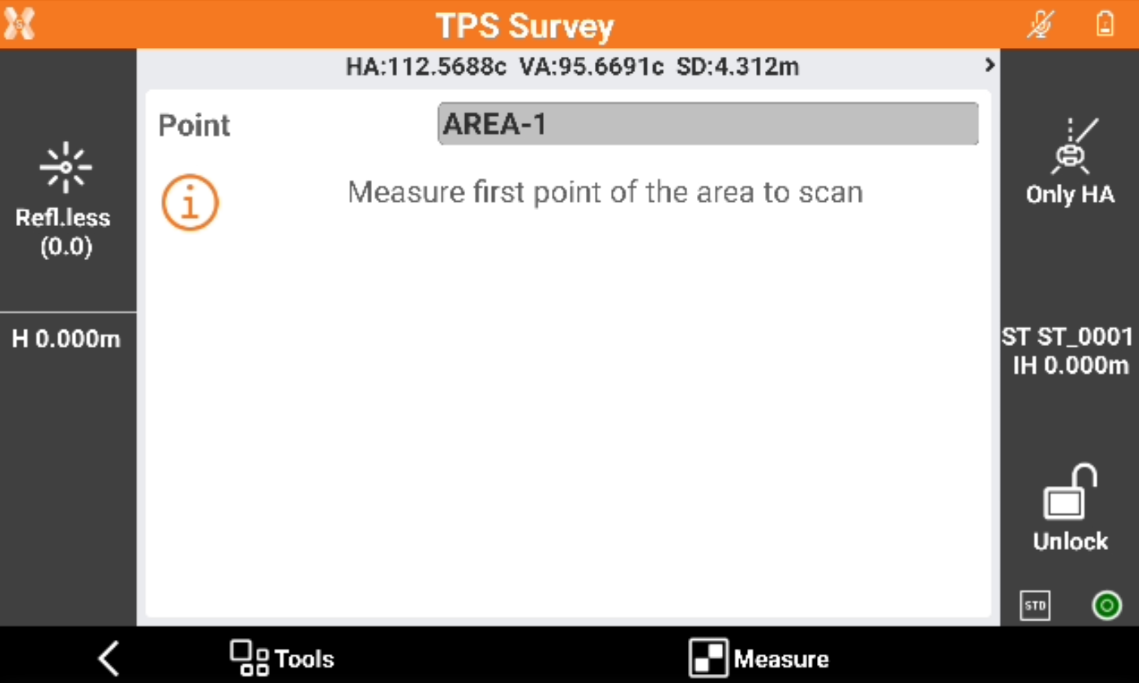
Select the Scan area.
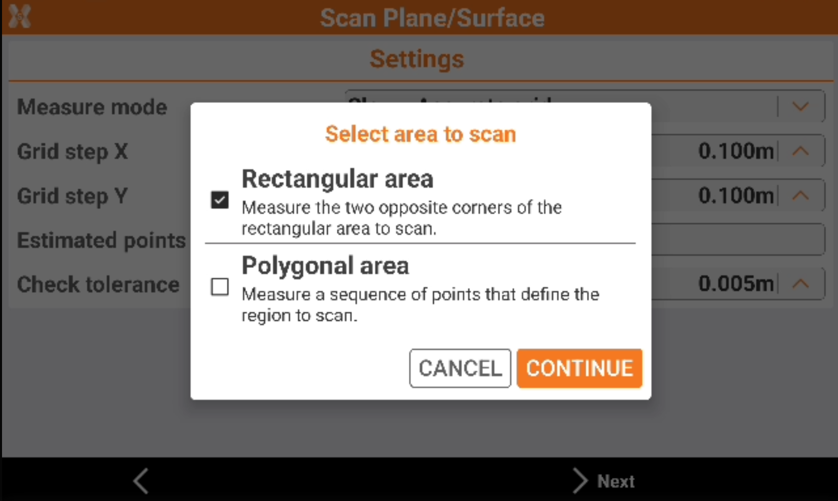
Rectangular area: the area to scan is a rectangle defined by measuring the two opposite corners of the rectangle.
Polygonal area: the area to scan is defined by measuring a sequence of points.
Click Next and measure the points to define the scan area.
Enter the scan Settings.
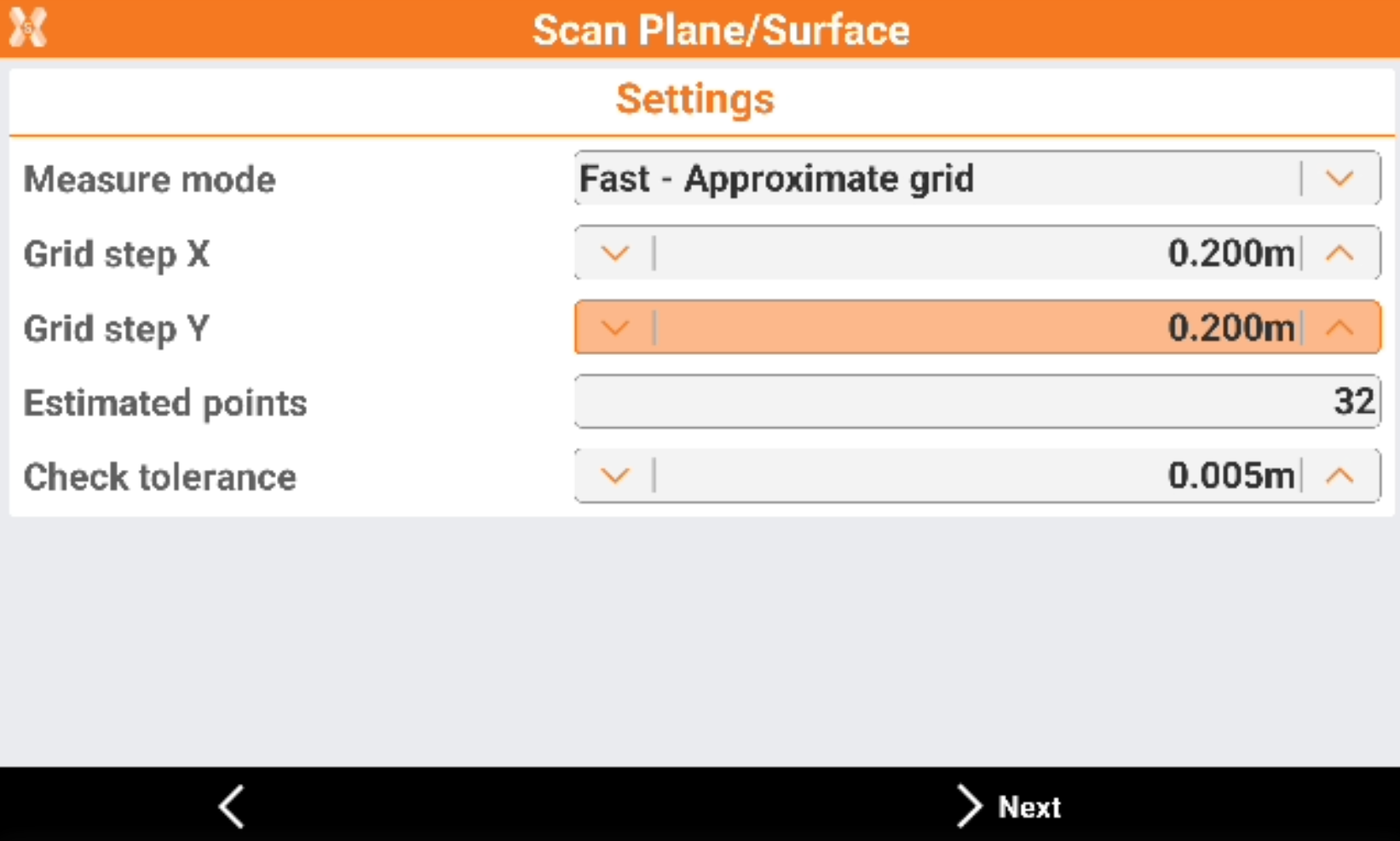
Measure mode: the scanning measure mode. Slower is the measure mode and more accurate is the distance between the points of the grid.
Grid step X: the grid step on the X component.
Grid step Y: the grid step on the Y component.
Estimated points: number of points that the software estimates to measure based on scan area and grid step.
Check tolerance: the tolerance to check for the measured points.
Click Next and press Start to start the scan.
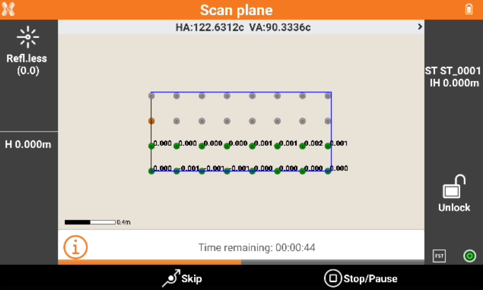
The software shows the grid of the points to measure.
Green points: measured points, the difference from the measured coordinate and the coordinate on the defined plane is visualized. The difference is within the tolerance.
Red points: measured points, the difference from the measured coordinate and the coordinate on the defined plane is visualized. The difference is over the tolerance.
Orange point: the point currently measured.
Grey points: the points still not measured.
Press Skip to skip the measure of the current point.
Press Stop/Pause to interrupt or pause the scanning.
When the scanning is completed the software shows the calculated surface with the contour lines.
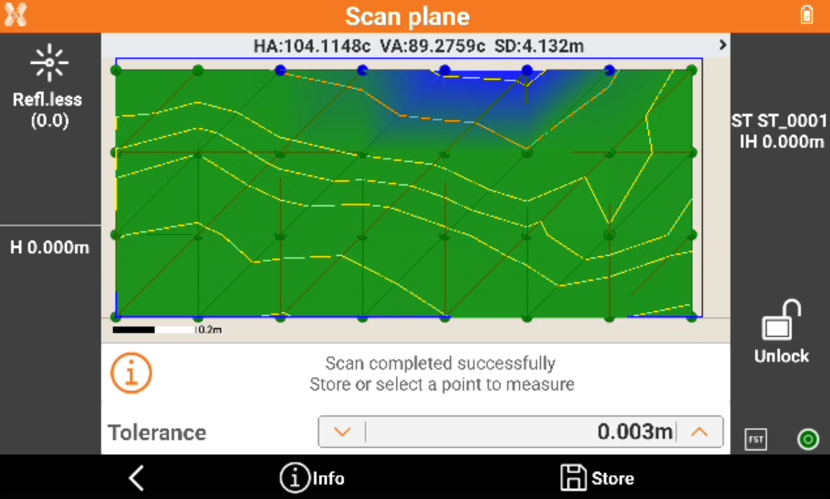
Click on a point in the graphic view to rotate the instrument to the point. Then click Measure to remeasure the point.
Click Info to open the information of the scanned object.
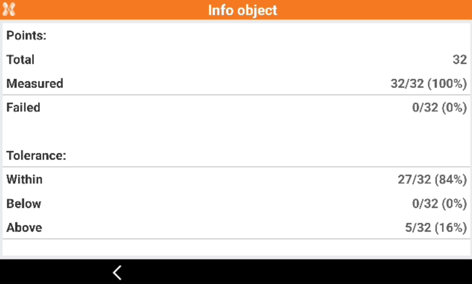
Click Store to store the results.
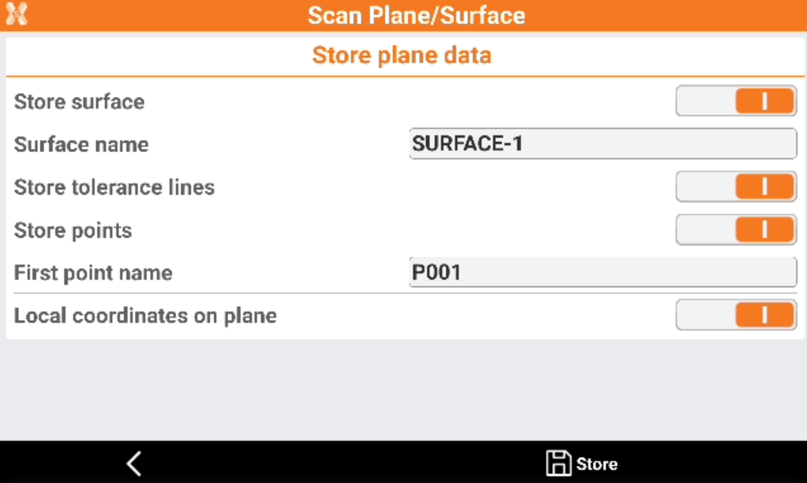
Store surface: allows to store the calculated surface in the current job.
Surface name: the name of the surface to store.
Store tolerance lines: the tolerance lines are stored in the current job.
Store points: all measured points are stored in the current job.
First point name: the name of the first stored point. The point name is then automatically increased.
Local coordinates on plane: if enabled, the points on the plane are in local coordinates.
Scan generic surface
Scan surface uses the motorized total station to perform an automatic measurement of a surface.
It is possible to define the area to scan (rectangular or polygonal), the grid size and the software will drive the Total station to measure each single point of the grid.
The result of the scan is a grid of points and a 3D surface that can be used for further calculations or can be exported to be used in different ways.
Click Survey.
Click Scan plane/surface.
Select Generic surface.
Select the Scan area.
Rectangular area: the area to scan is a rectangle defined by measuring the two opposite corners of the rectangle.
Polygonal area: the area to scan is defined by measuring a sequence of points.
Click Next and measure the points to define the scan area.
Measure the points that define the area to scan. Click Back to complete the definition.
Measure a point that defines the average distance of the surface from the instrument.
Enter the scan Settings.
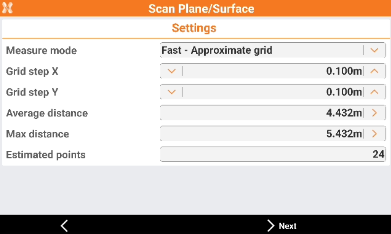
Measure mode: the scanning measure mode. Slower is the measure mode and more accurate is the distance between the points of the grid.
Grid step X: the grid step on the X component.
Grid step Y: the grid step on the Y component.
Average distance: the average distance from the instrument to the surface to scan.
Max distance: the maximum distance from the instrument to the surface to scan.
Estimated points: number of points that the software estimates to measure based on scan area and grid step.
Click Next and press Start to start the scan.
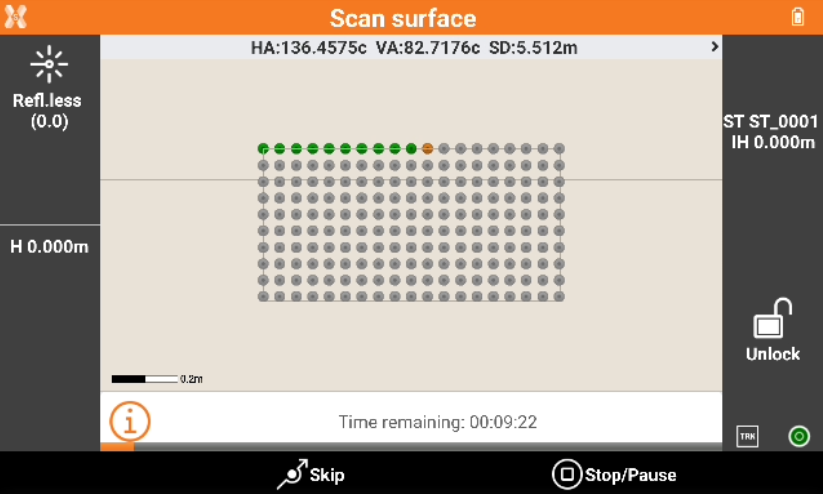
The software shows the grid of the points to measure.
Green points: measured points,.
Orange point: the point currently measured.
Grey points: the points still not measured.
Press Skip to skip the measure of the current point.
Press Stop/Pause to interrupt or pause the scanning.
When the scanning is completed the software shows the calculated surface with the contour lines.
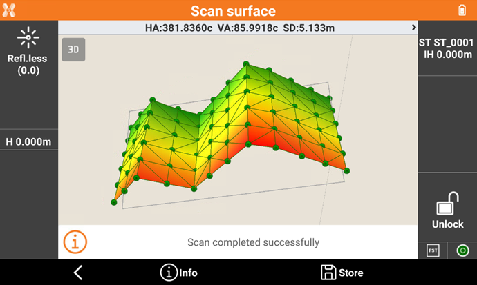
Click on a point in the graphic view to rotate the instrument to the point. Then click Measure to remeasure the point.
Click Info to open the information of the scanned object.
Click Store to store the results.
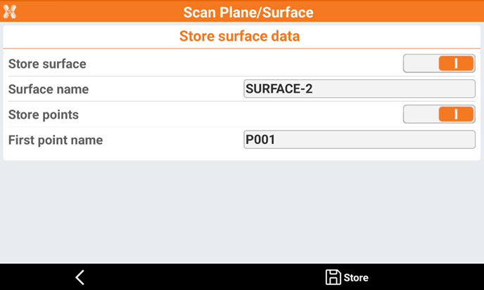
Store surface: allows to store the calculated surface in the current job.
Surface name: the name of the surface to store.
Store points: all measured points are stored in the current job.
First point name: the name of the first stored point. The point name is then automatically increased.