TPS settings
 |
|  |
| 
The tab allows to set the total station survey functioning and control parameters.
Click Settings.
Click TPS.
TPS tab
The TPS tab allows to edit the accuracy setting for the TPS measurements and change some general settings when working with TPS.
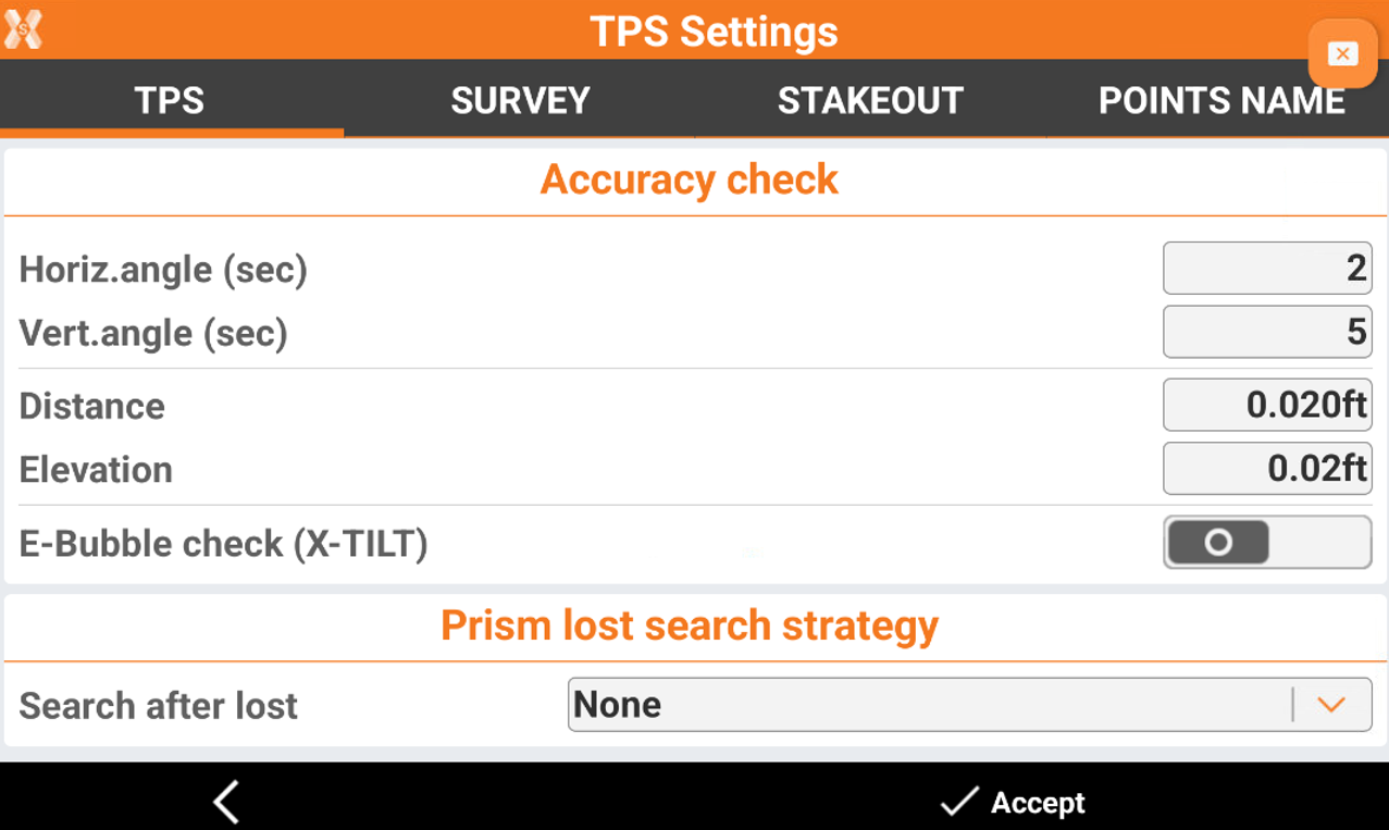
Accuracy check
Horiz.angle (sec)/Vert.angle (sec): tolerance for distances and elevations If a measurement differs from the average value more than the defined tolerance, it is highlighted in the list of measurements.
Distance: maximum acceptable error in distance for multiple measurements in face 1 and face 2.
Elevation: maximum acceptable error in elevation for multiple measurements in face 1 and face 2.
E-Bubble check (X-TILT): activates the use of electronic bubble. The electronic bubble is visualized in the survey and stakeout windows.
Max error (2m pole): maximum error acceptable outside the bubble considering a 2 meter pole if the E-Bubble check (X-TILT) is activated.
Prism lost search strategy
Search after lost: activates the automatic search of the prism after the total station lost it. When the prism is lost, the TPS goes in prediction mode for 3 seconds. After that time, if the prism is not yet recognized, the automatic search starts immediately. The searching modes are:
None: no action.
360° search: a 360° search of the prism is started.
Win + 360°: a window search in the zone where the prism is lost is started followed by a 360° search.
Return to last pos: the station goes in the last position where the prism was locked.
Use controller's GNSS: use the GPS location of the controller to search for the prism.
Skip lock on Control points: on construction sites, reference points are usually in fixed positions and stored as control points in X-PAD Ultimate to be used for station setup and orientation. This option allows automatic exclusion of all control points stored in the job file from target lock. If the TPS locks onto one of these targets, it will automatically unlock and continue searching for the prism on the pole.
Miscellaneous:
TPS symbol 3D: enables the display of a 3D symbol for the instrument, when the 3D view is active in the survey and stakeout graphics window.
Photos store mode: decide which pictures to store in case pictures are taken during the survey.
All photos: all photos are stored.
Only low res. photo: only low resolution photos are stored.
Only high res. photo: only high resolution photos are stored.
Only geo tagged photo: only geo tagged photos are stored.
Target height immediate keyboard: when enabled and the target height is selected, a keyboard appears from which new values can be inserted. Otherwise, the value for the target height must be selected from a table.
Free station in F1/F2: enables the measurement of the reference point in free station setup in direct and reverse face in order to assure maximum accuracy.
Free station - set horizontal angle to azimuth: if enabled, after free station calculation is performed, applies to the TPS horizontal angle the calculated azimuth value.
Survey tab
The tab allows to set the main functioning parameters for the different TPS survey modes.
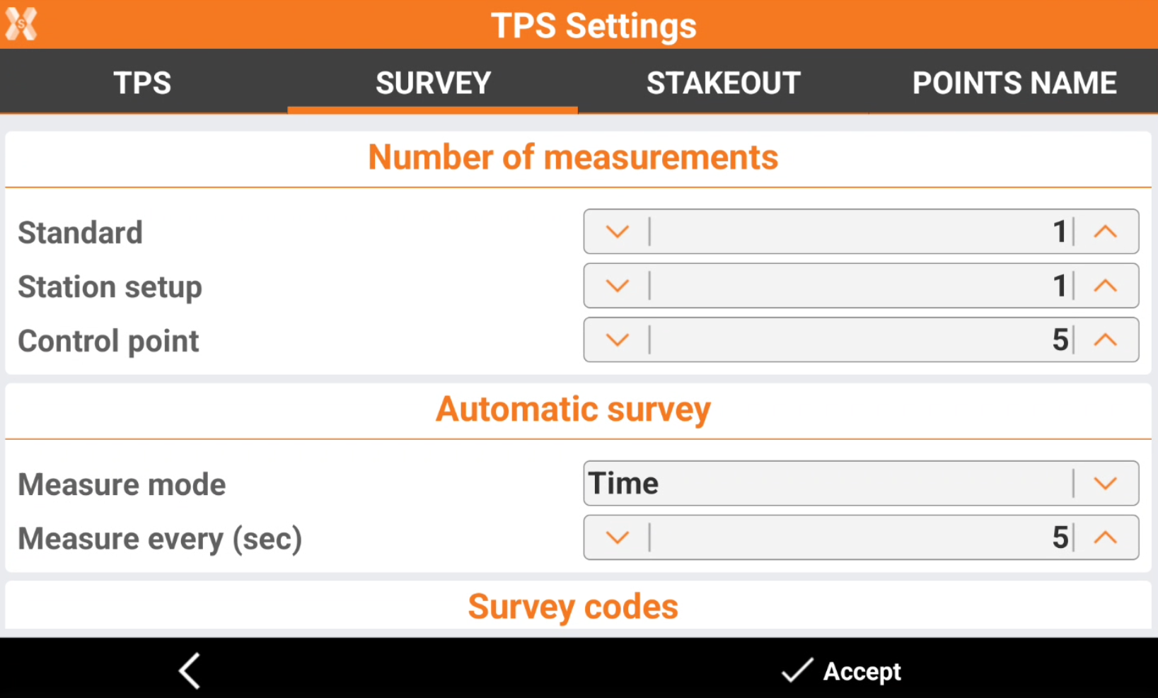
Number of measurements
Standard: sets the number of measurements that the TPS must perform before storing a point.
Station setup: sets the number of measurements to use in setup operations.
Control point: sets the number of measurements that the TPS must perform before storing a point of type control point.
Automatic survey
Measure mode: mode to use for the automatic points survey:
Time: position is acquired at intervals of time.
Distance 2D: position is acquired at intervals of horizontal distance.
Distance 3D: position is acquired at intervals of three-dimensional distance.
Distance 2D Plus: position is acquired at intervals of horizontal distance and height difference according to settings.
Stop & Go: position is acquired according to Stop & Go mode. When the pole remains static, the software begins to acquire the position.
Measure every (sec): In case of Time mode: Defines the interval of time between the automatic acquisition of positions.
Distance 2D: in case of Distance 2D mode. Defines the interval of horizontal distance that must be between the position to acquire and the position previously acquired.
Distance 3D: in case of Distance 3D mode. Defines the interval of three-dimensional distance that must be between the position to acquire and the position previously acquired.
Distance 2D Plus: in case of Distance 2D Plus mode. Defines the interval of horizontal distance and the height difference that must be between the position to acquire and the position previously acquired. The point is acquired when one of the values is exceeded.
Stop time (sec): in case of Stop & Go mode. Defines the time to stay on the point to allow the acquisition of position.
Max pole movement: in case of Stop & Go mode. Represents the maximum movement allowed to consider the pole static. When the software identifies that the pole remains in static position with a movement lower than the maximum value, the acquisition of the position begins for the defined time.
Survey codes
Numeric codes: activates a preferential use of numeric codes concerning survey codes. The virtual keyboard appearing is the numeric one.
Measure after Quick Code: when activated, measurements start immediately automatically after the selection of the Quick Code.
Add new codes to library: when activated, a code used during the surveying that is not store in the library yet, is added automatically.
GIS line attributes:
For all points: GIS attributes are required for each point of the line.
To first point: GIS attributes are required for the first point of the line.
To last point: GIS attributes are required for the last point of the line.
Smart drawing lines (advanced): enables the use of linework when surveying with lines.
Average coordinates
Average coords: activates the calculation of the average point coordinates when measured multiple times.
Max H/V: tolerance for distances and elevations If a measurement differs from the average value more than the defined tolerance, it is highlighted in the list of measurements.
Miscellaneous
Survey display mode: sets the default display mode of the survey graphics window performed with total station.
2D (TPS direction): displays items of drawing and surveying in 2D oriented mode according to the direction of the total station.
2D (north): displays items of drawing and surveying in 2D oriented mode according to North.
3D (walk direction): displays items of drawing and surveying in 3D oriented mode according to the direction of the TPS. The program shows the direction based on the position of the controller, which can be behind the TPS or behind the pole.
Stakeout tab
The tab allow to set the functioning and control parameters for the TPS stakeout.
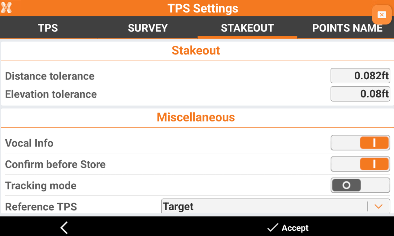
Tolerance
Distance tolerance: maximum horizontal distance between current position and stakeout position. If the distance between current position and position to reach is lower than or equal to the tolerance, the software reports the reaching of stakeout position.
Elevation tolerance: maximum acceptable difference between current elevation and stakeout elevation If the elevation difference is lower than or equal to the tolerance, the software reports the reaching of the position in elevation.
Miscellaneous
Vocal Info: activates the vocal information during the stakeout operations.
Confirm before Store: allows checking the stakeout position before proceeding to saving the new point on position to stakeout. When disabled, the stakeout point is saved without any further request.
Tracking mode: when activated, the tracking mode is always set with the continuous surveying mode.
Reference TPS: defines the reference to which the information to reach the stakeout position with the total station is provided. References can be:
Target: information is provided considering the operator on the target looking toward the total station.
Total station: information is provided considering the operator on the TPS position.
North: information is provided referring to North.
Current direction: information is provided referring to the current walking direction.
Point: information is provided referring to a reference point.
Previous point: information is provided referring to the previous stakeout point.
Reference line: information is provided referring to a reference line.
Turn to stakeout point: when activated, the motorized total station turns automatically toward the stakeout point when selected.
No: the automatic turn to the stakeout point is disabled.
3D (horiz & vert): the automatic turn to the stakeout point is enabled. The motorized total station turns toward the stakeout point considering the point position and elevation.
2D (horiz only): the automatic turn to the stakeout point is enabled. The motorized total station turns toward the stakeout point considering the point position only.
Stakeout display mode: sets the default display mode of the stakeout graphics window performed with the total station
2D (TPS direction): displays items of drawing and staking out in 2D oriented mode according to the direction of the total station.
2D (north): displays items of drawing and staking out in 2D oriented mode according to North.
3D (TPS direction): displays items of drawing and staking out in 3D oriented mode according to the direction of the TPS. The program shows the direction based on the position of the controller, which can be behind the TPS or behind the pole.
Points name tab
| |
The window allows the customisation of point names according to the type of point. If the point name is composed of letters and numbers, the program only increases the numerical part during operations.
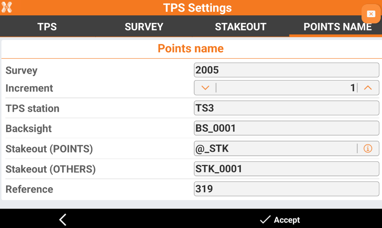
Points name
Survey: the starting name for surveying points.
Increment: the increase of the numerical part of the name.
TPS station: the name of TPS stations.
Backsight: the name of backsight points.
Stakeout (points): the name of stakeout points. The symbol @ if used in the field will be automatically replaced by the name of the staked point. If @ is not entered, then the name of the stored point will not include the name of the original staked point.
Stakeout (others): the name of other stakeout elements.
Reference: the name of reference points.