
-
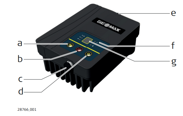
Components of the TRU35 radio.
-
High/low power switch: switch between high and low transmitting power.
-
Power on/off: turns on/off the radio.
-
Port 1: 5 Pin power/serial port: to connect the cable to external power and GNSS base receiver.
-
Channel switch: switch radio working channel.
-
Port 2: TNC Radio antenna interface: to connect radio antenna.
-
LED indicators: LED indicators for information on the radio status.
-
Display: indicates the channel in use.
-
Keyboard
-
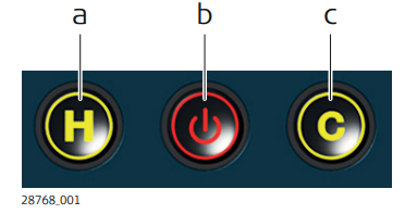
Keyboard is used to power on/off the radio, and switch channel and power.
-
Power on/off: turns on/off the radio.
-
High/low power switch: switch between high and low transmitting power.
-
Channel switch: switch radio working channel. Only TX channel can be switched.
-
LED indicators
-
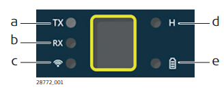
The TRU35 has Light Emitting Diode indicators. They indicate the basic instrument status.
-
Data transmission LED:
-
Flashing green: flashes according to the transmission frequency. The default status is off.
-
-
Data reception LED:
-
Flashing green: flashes according to the receiving frequency. The default status is off.
-
-
Connectivity LED:
-
Solid blue: radio is connected.
-
Off: radio is not connected.
-
Flashing blue: data transmission.
-
-
High/low power LED:
-
Green: high power.
-
Off: low power.
-
-
Power LED:
-
Solid green: power on.
-
Flashing green: warning. Voltage < 11.3 V: Normal data transmission. Voltage < 10.5 V: Data transmission stops. Temperature > 90 °C: Data transmission stops.
-
-
Display
-
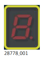
The digital display on the TRU35 panel shows the current transmitting channel. The Transmitting frequency is generally different for different channels.
-
1 - 9 - 0 (channels 1 - 10) a - f (channels 11 - 16).
-