Alignment main settings
The Main settings page allows to change the main settings of alignments and cross sections.
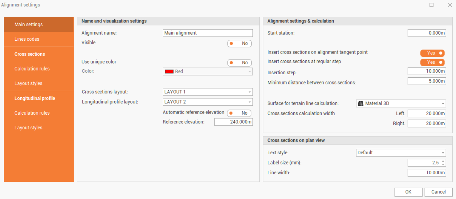
Name and visualization settings: allows to change how cross sections and alignments are visualized.
Alignment name: the name of the alignment.
Visible: set the alignment visible or not visible in CAD, the sub-project is turned off.
Use unique color: enables/disables the use of a unique color for all the cross sections in the group in CAD instead of the color defined in the relative layer.
Cross sections layout: allows to choose the cross sections layout from the list of available layouts (see Group of sections layout styles).
Longitudinal profile layout: allows to choose the longitudinal profile layout from the list of available layouts (see Group of sections layout styles).
Automatic reference elevation: enables/disables the automatic definition of the cross sections reference elevation to be used for longitudinal profile, depending on the cross section elevations. If it is disables it is possible to manually define the reference elevation.
Alignment settings & calculation: allows to define how the cross sections are created along the alignment.
Start station: the starting station along the alignment.
Insert cross sections on alignment tangent point: automatically creates cross sections on the tangent points on the alignment, for example starting and ending curve.
Insert cross sections at regular step: automatically creates cross sections at a regular step, defined in Insertion step.
Insertion step: the step for automatically insertion of cross sections along the alignment.
Minimum distance between cross sections: allows to define the minimum distance between two cross sections to prevent to have cross sections too close.
Surface for terrain line calculation: select the surface subproject for the terrain line calculation.
Cross sections calculation width: allows to select the width of the cross sections.
Cross sections on plan view: these settings are related to the cross section labels in CAD.
Text style: the text style used for cross section labels in CAD view.
Label size (mm): the text size in mm used for cross section labels in CAD view, the size on-screen depends on the drawing scale factor.