CAD view in survey and stakeout functions
 |
|  |
| 
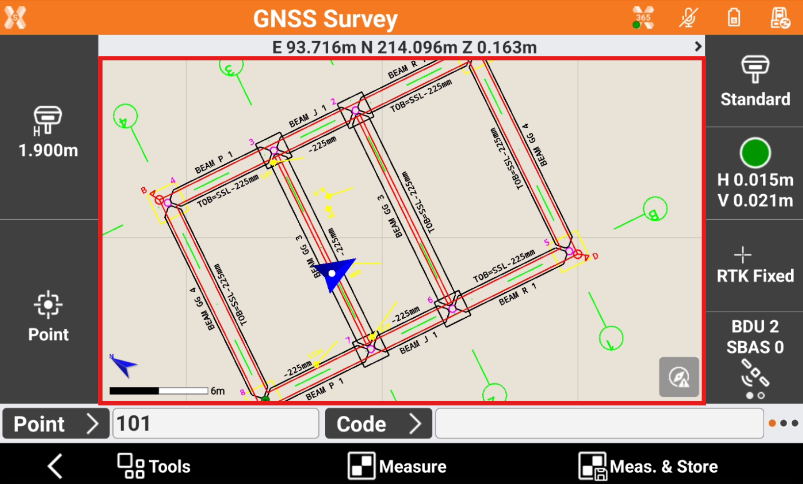
In survey and stakeout functions the software offers a CAD view where the current instrument position is visible in a CAD view, with measured points and all graphic entities.
CAD buttons
The CAD buttons are the same as available in the main CAD window.
Click in the graphical windows of the drawing display. The buttons and commands for displaying the drawing are activated.
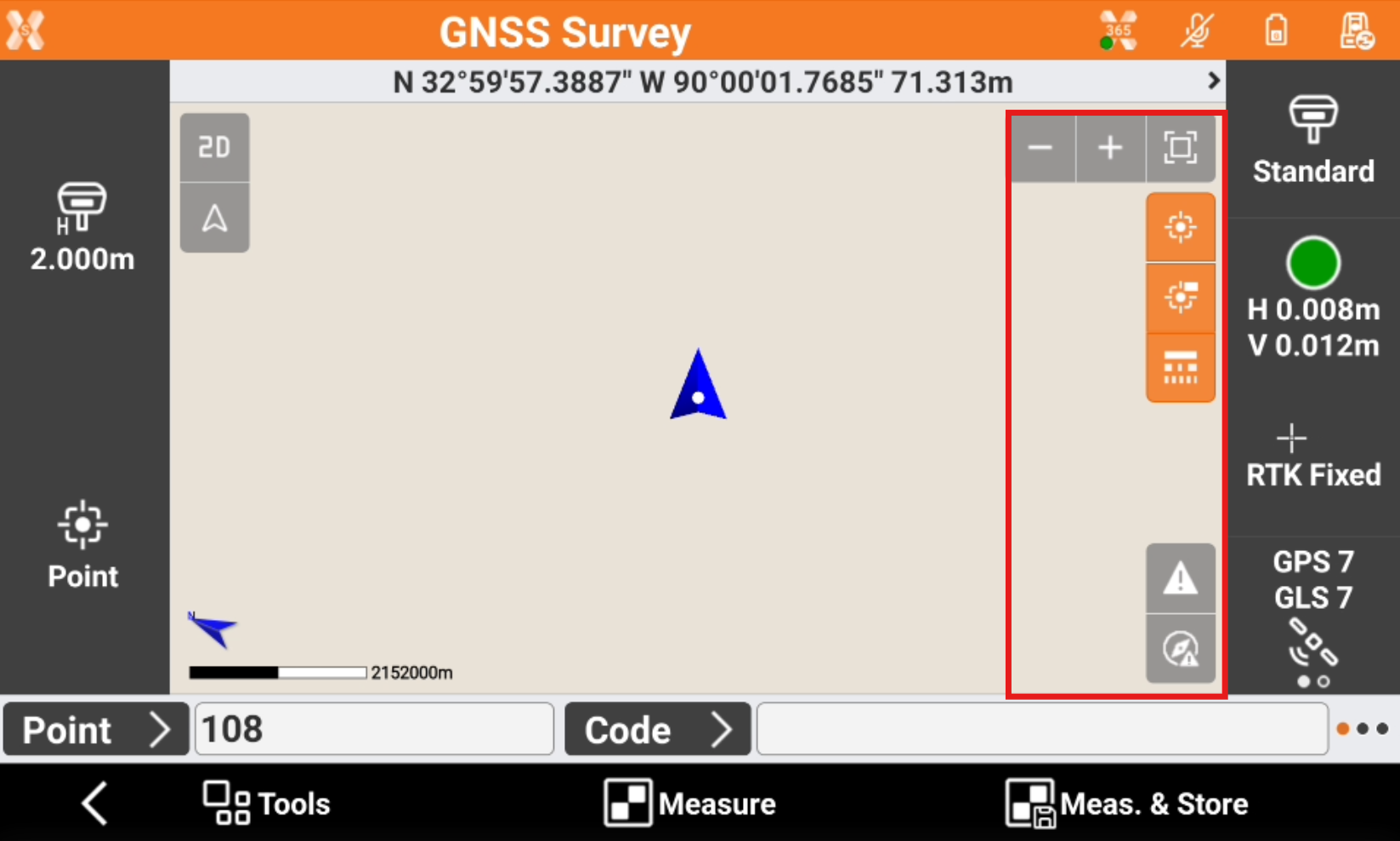
Zoom all
 : displays of all the drawing elements.
Zoom window
 : allows to specify the visualization area through indication of the opposite angles.
Zoom in
 : enlarging the visualization.
Zoom out
 : reducing the visualization.
Points
 : enables and disables the visibility of points.
Points labels
 : enables and disables displaying point labels.
Linetype
 : enables and disables the visibility of linetypes.
Working area
 : the icon notifies that the drawing extension is too large to display all elements appropriately. Open the CAD to define the working area.
Controller not calibrated
 : notifies that the compass of the controller is not calibrated and it is required to perform the calibration procedure. Tap the icon to perform the calibration procedure by the movement showed in the following image.
Commands
Pan: shifting of the view is always active. Click in the graphic area and drag the view.
Pinch out : tap in the graphic area using two fingers and spread them on the screen.

Pinch in: tap in the graphic area using two fingers and merge them on the screen.

Double click: opens the main CAD.
Display mode
Press on screen to open the toolbar and change the display mode.
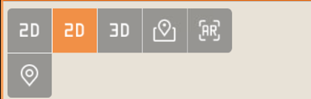
2D
 : enables 2D drawing display. See 2D view.
3D
 : enables 3D drawing display. See 3D view.
Maps
 : enables 2D display of a reference map. See Online maps view.
Augmented reality
 : enables the use of augmented reality. See Augmented reality
GPS direction
 : enables the automatic update of the view oriented to the direction of the antenna.
TPS direction
 : enables the automatic update of the view oriented to the direction of the instrument.
GPS north direction
 : enables the automatic update of the view oriented to North.
TPS north direction
 : enables the automatic update of the view oriented to North.
Manual view
 : allows to manually change the view disabling the automatic view.