Create a code
 |
|  |
| 
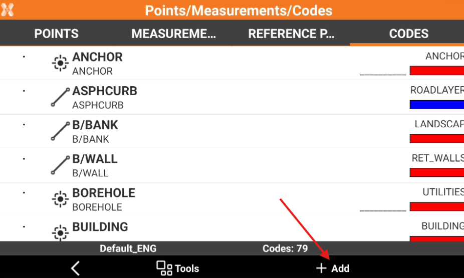
To create a new code from the Survey codes page click Job.
Click Points/Measurements/Codes.
Open the Codes tab.
Click Add.
The data of the code is organised in pages.
Main data page
This page allows to enter code name, description and drawing type.
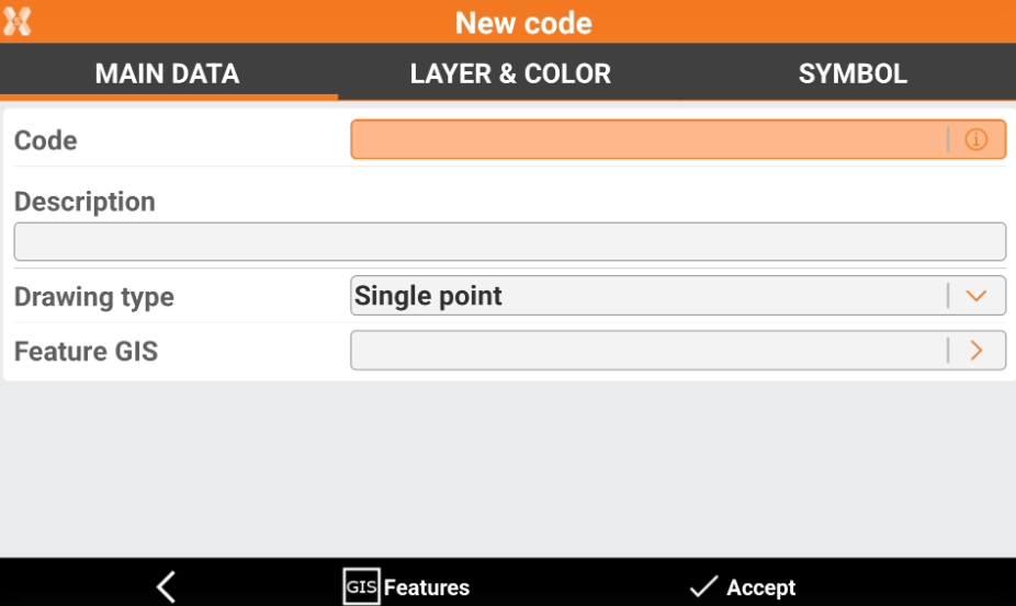
Code: name of the code. For a parametric codes use symbol # in code name to pass a value from code name to description automatically. For example code “D#” and description “Distance #cm”: entering in application code “D25” will result in description “Distance 25cm”.
Description: extended description.
Drawing type: defines how the measured object is shown in graphics.
Single point: a single position is used, for example for a tree or an illumination pole.
Line: a polyline is used, for example for the side of a road or a wall.
Square diagonal: a square is used inserted at the opposite end of the measured point.
Square center: a square is used inserted at the centre of the measured object or in the middle of a measured line.
Rectangle base: a rectangle is used inserted at the opposite end of the measured point of the base and a point on the opposite side.
Rectangle center: a rectangle is used inserted at the centre, the middle point on a side and a third point on the other side.
Circle 3P: a circle is used inserted by measuring three points on the circumference.
Circle center: a circle is used inserted by measuring the center point and a point on the circumference.
Spline: a spline is used.
Control point: a control point measurement is used.
GIS features: one of the GIS features from the current job can be assigned to the point. More information can be added defined by the properties of the associated GIS feature.
Layer & color page
These are the settings for the single layer. When creating a layer, the default settings saved in the main Settings page are displayed. The settings here can be changed.
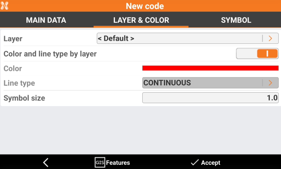
Layer: layer linked to point.
Color and line type by layer: the color and line type of the layer is used for the drawing of the point symbol and its line type.
Color: color used for the point symbol if the layer color is not used.
Line type: line type used if the line type by later is not used.
Symbol size: dimension of the symbol.
Click on the arrow near the Layer to open the Layer manager.
Click on the arrow near the Line type to open the Line types manager.
Click GIS Features button to open the GIS features manager.
Symbol
This page allows to assign a symbol to a code. It is possible to use default symbols or import new symbols from DWG file.
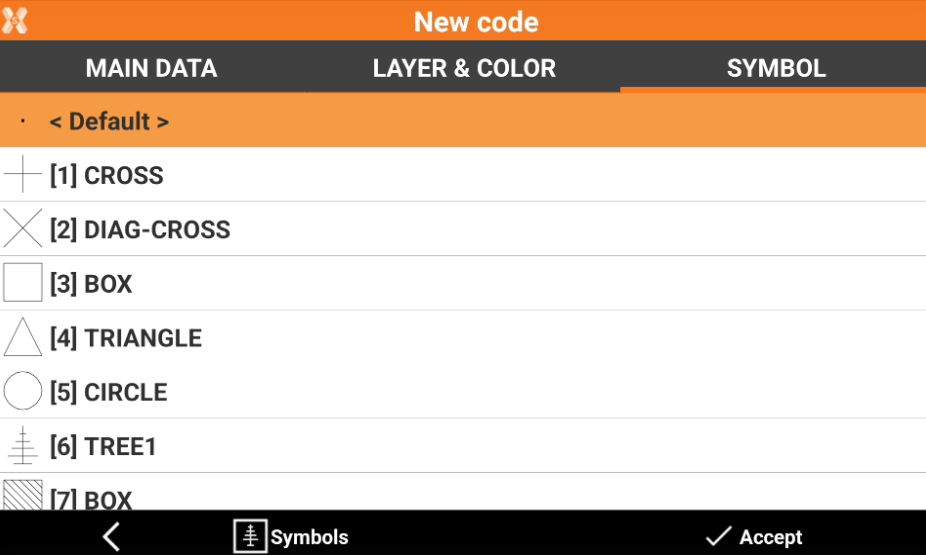
Select a symbol used to draw the point to which the code is associated from the list.
Click Symbols button to open the Symbols manager and importing new symbols.