Edit a road
 + ROAD |
  + ROAD
The available roads are listed in the Road Manager.
To edit a road, from Road Manager click on the road to edit.
Click Modify.
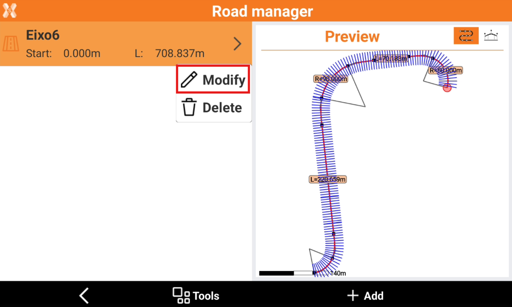
This open the road editing page.
The stations unit can be changed in Units.
The pages Cross section templates, Widening and Superelevation have to be used to design cross sections in case the only information available is the centerline. If the cross sections or the road edges are available in the project, these pages have not to be used.
Road page
The Road page includes the main information regarding the road.
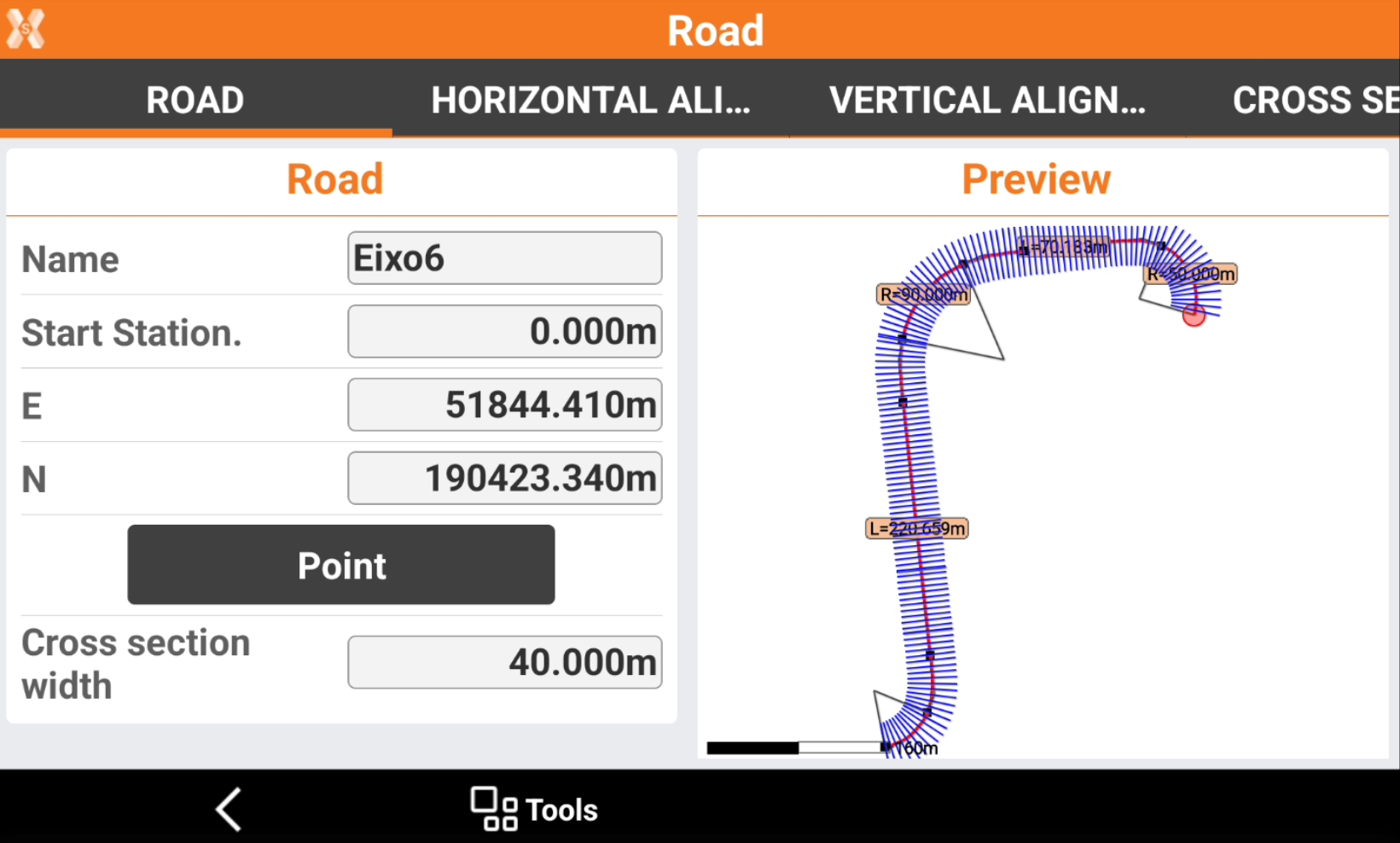
Name: the name of the road.
Start Station: the starting station of the road.
E, N: the coordinate of the starting station.
Point: click here to select the starting point from CAD or from the list of available points.
Cross section width: defines the cross section width, used by the software to to draw cross sections along the horizontal axis.
Click Tools and Play to open the Play cross sections page.
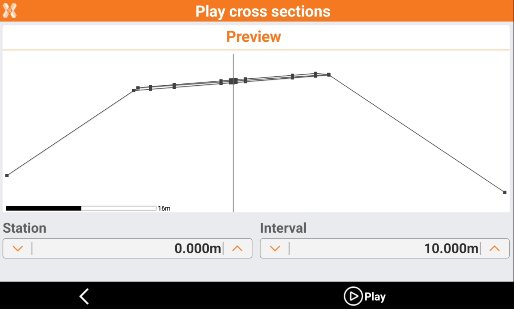
The page shows the cross sections at the change of station.
Station: enter the starting station.
Interval: the station interval to show the different cross sections.
Click Play to automatically show the cross sections at the change of station.
Horizontal alignment
The page lists the horizontal alignment elements.
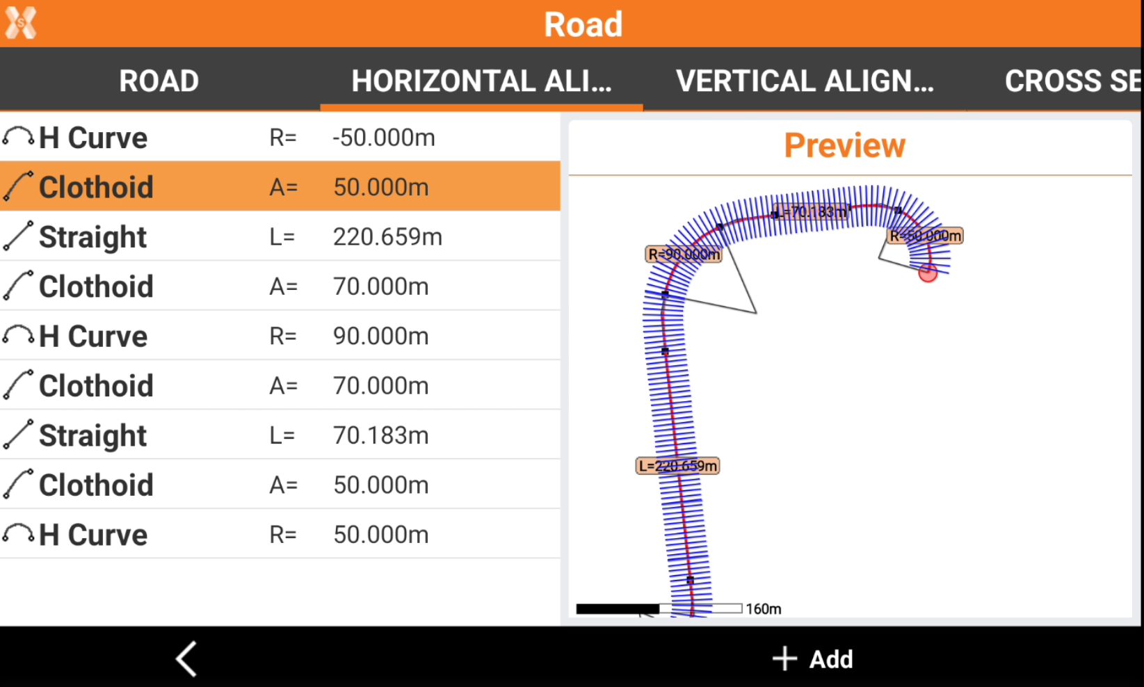
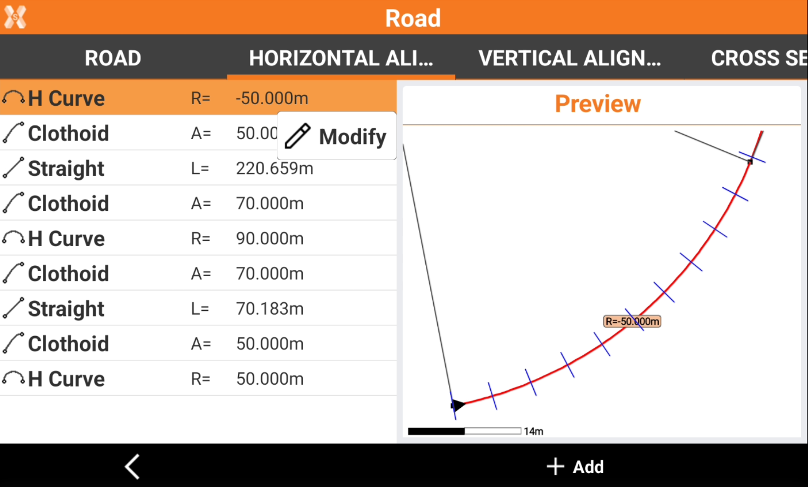
Click on an element to zoom in the preview panel.
Click Modify to edit the selected element.
Click Add to add an horizontal alignment element, in case the road has to be designed in the field.
Refer to Design a road step-by-step for more information on how edit or add an horizontal alignment.
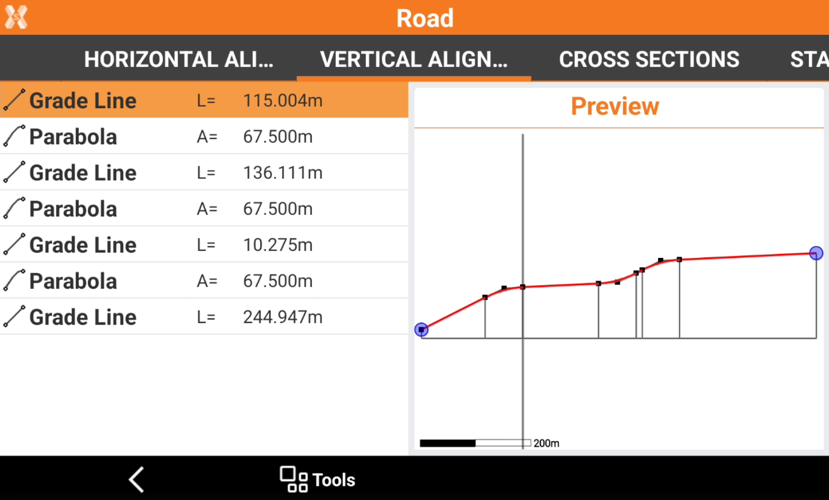
Vertical alignment
The page lists the vertical alignment elements.
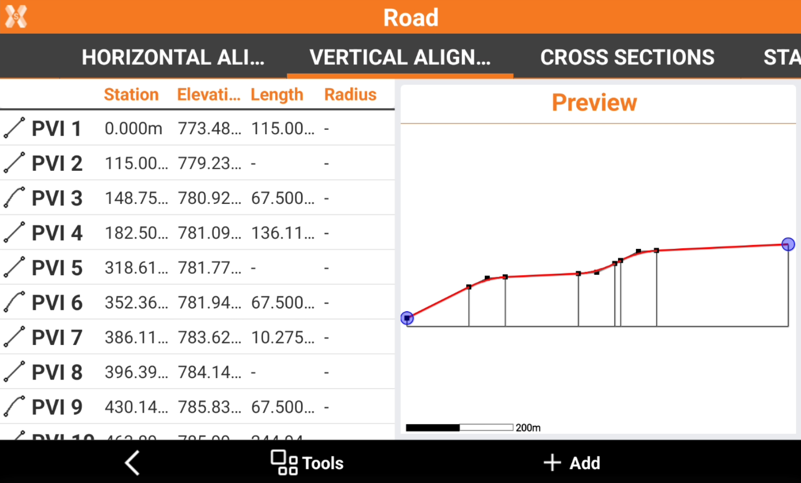
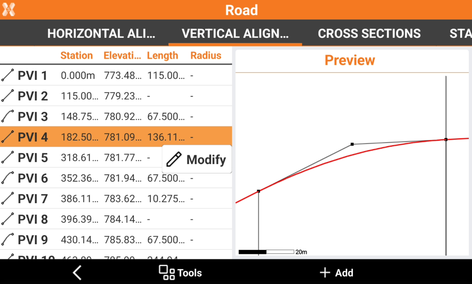
Click on an element to zoom in the preview panel.
Click Modify to edit the selected element.
Click Add to add a alignment element, in case the road has to be designed in the field.
Refer to Design a road step-by-step for more information on how edit or add a vertical alignment.
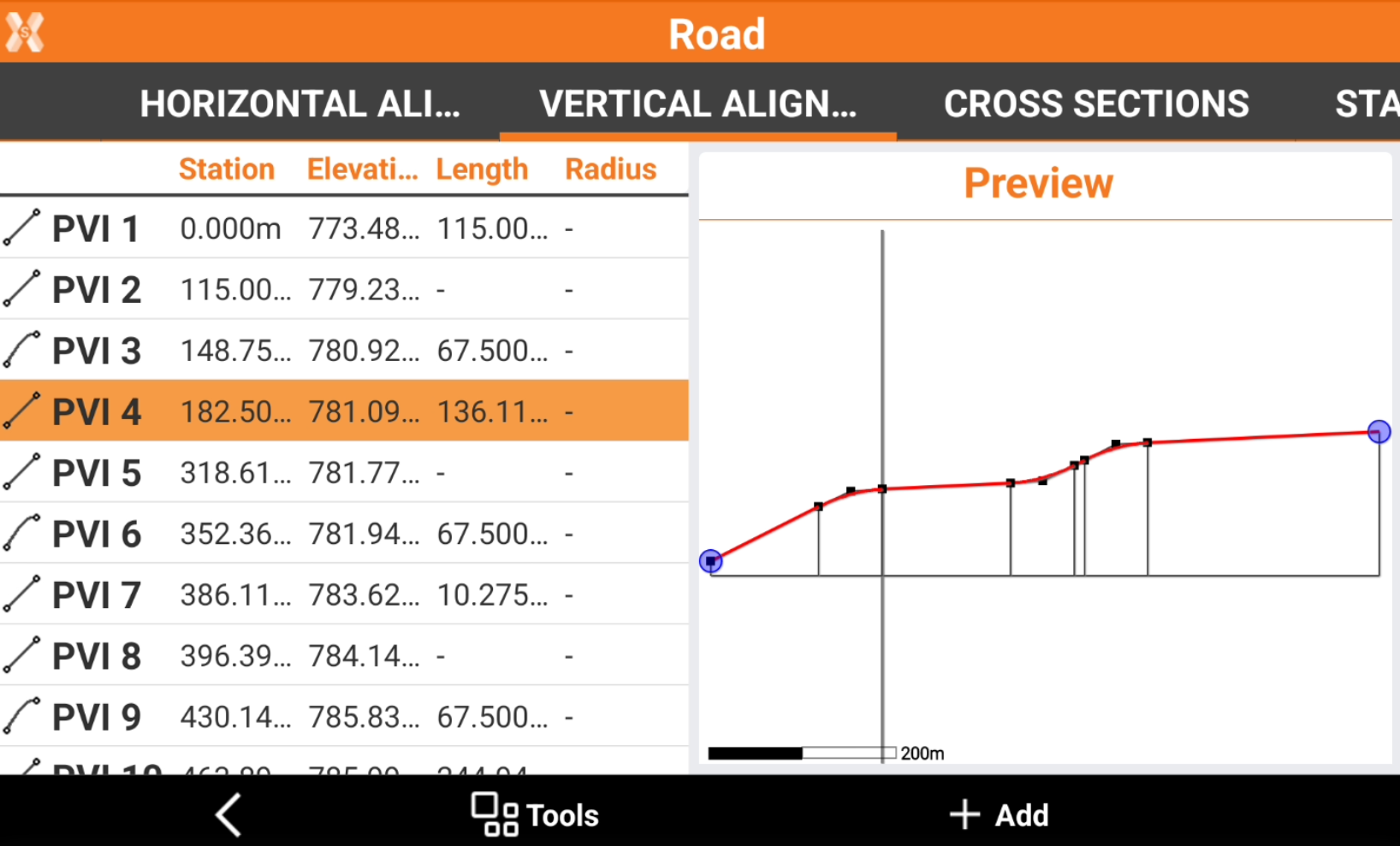
Click Tools and Vertical element list to show the list of vertical alignment elements.
Click Tools and PVI list to show the list of PVI.
Cross sections page
This page lists the imported cross sections.
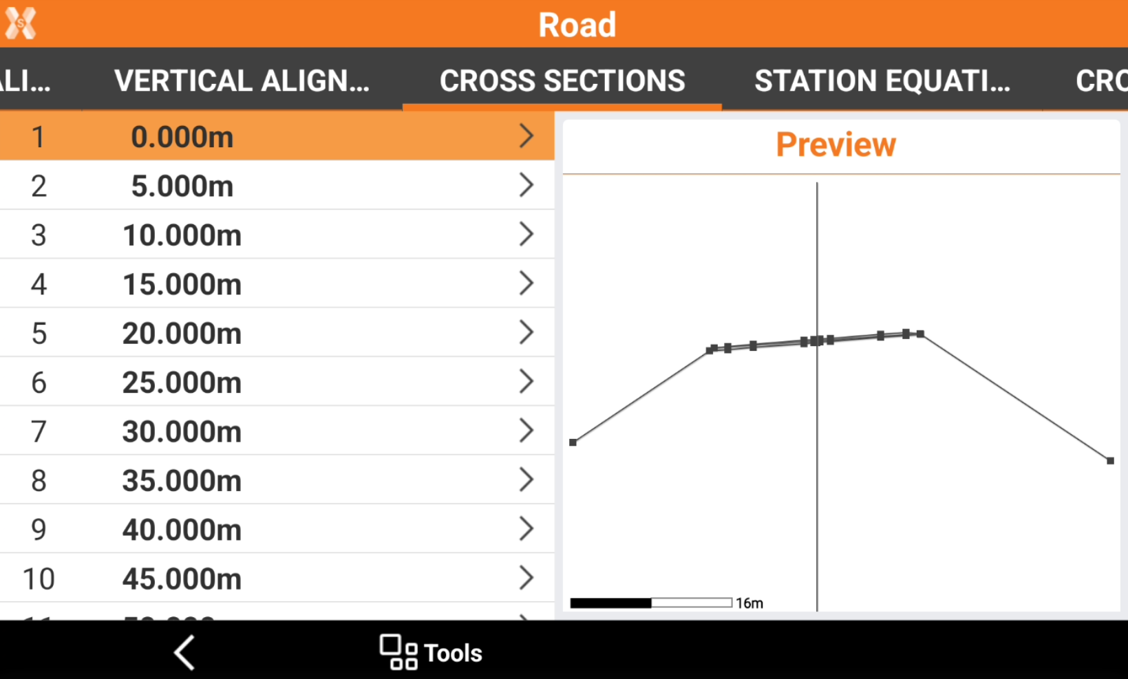
Click on a specific cross section to display the cross section in the preview panel.
Click on a specific cross section and click View to show the list of cross section vertexes and the layers.
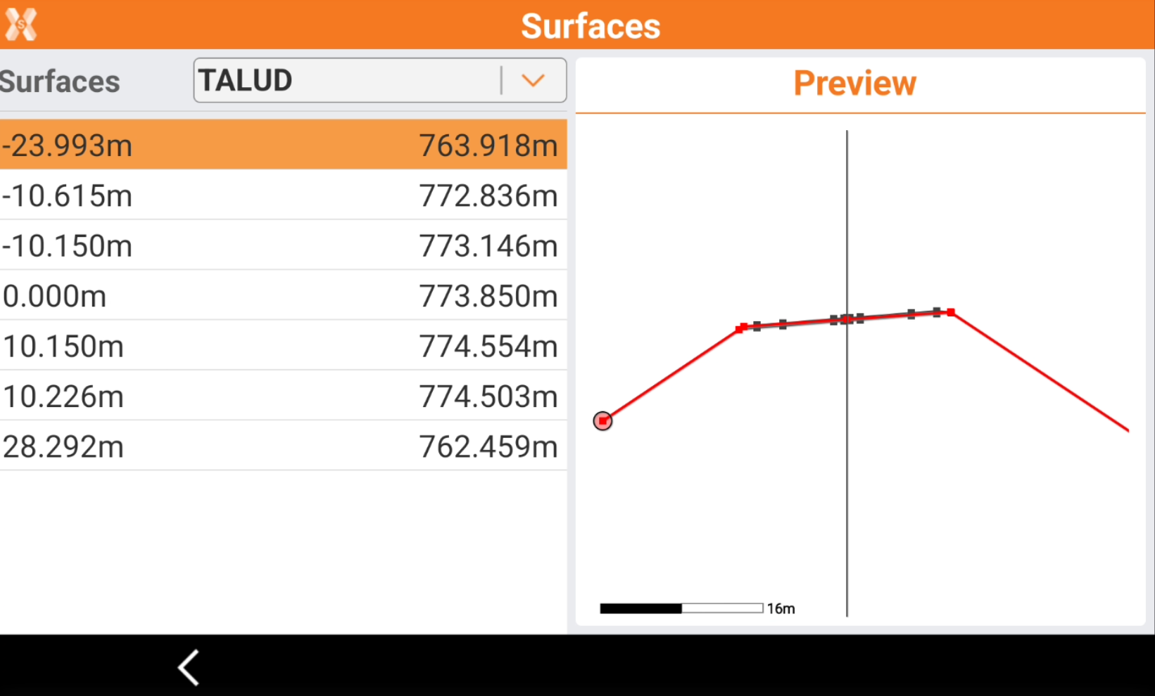
Click Surfaces to change layer.
The left panel lists the vertexes of the cross section with horizontal offset and elevation.
Station equation page
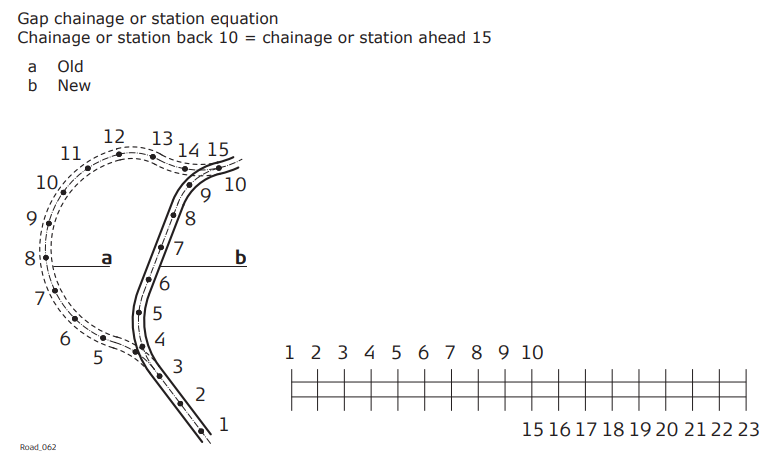
Forward and backward station equations are available to adjust stations along an alignment. Chainage or station equations are used to adjust the alignment chainage or station.
The most common reason for doing so is the insertion or removal of curves during the design process.
Inserting or removing a curve would require recalculating the chainage or station of an entire alignment. Using chainage or station equations eliminates this need.
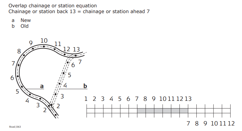
Chainage or station equation can create either a gap or an overlap as shown in the following diagrams.
Click Add to create a new station equations.
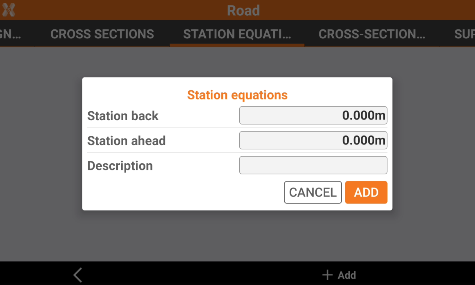
Station back: the previous station that is replaced by the station ahead.
Station ahead: the station ahead.
Description: field for a description.
Click Add to add the new station equation.
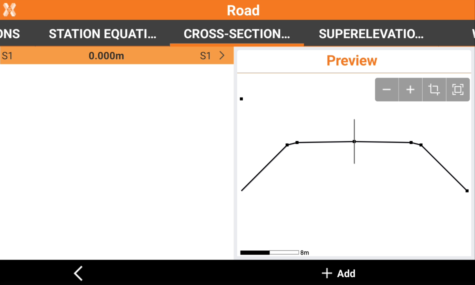
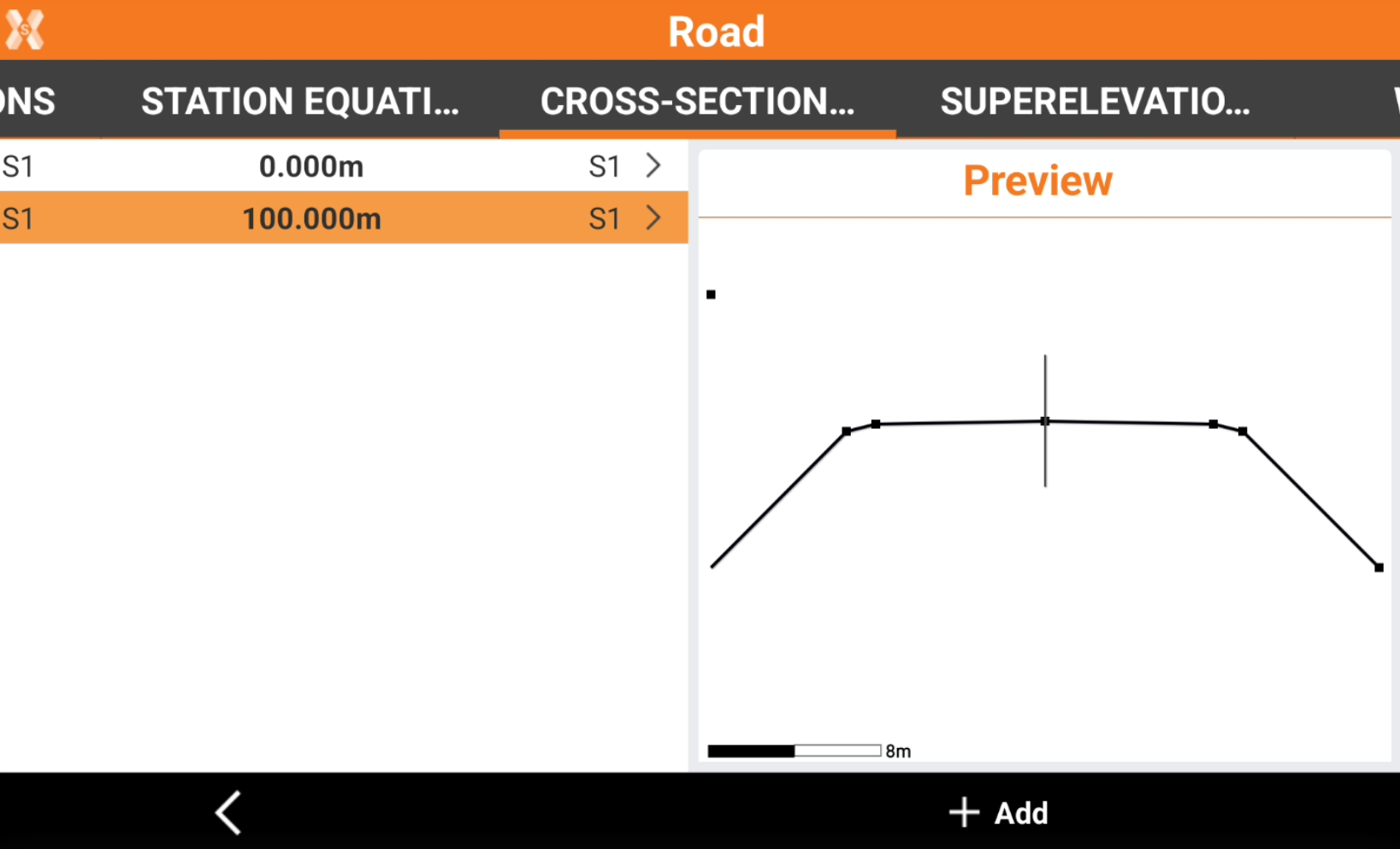
Cross section template page
The page lists the cross section templates that have been manually assigned to the selected road.
This allows to apply cross sections to a road when designing a road.
The cross section templates are designed in X-Sections template page.
Click Add to add a new template.
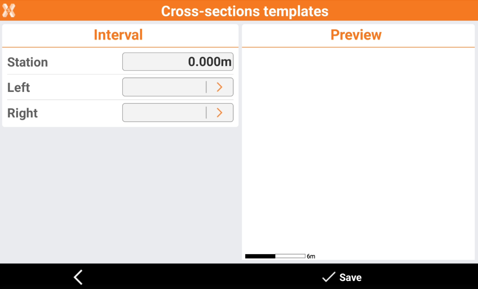
Station: the station where to apply this cross section.
Left: the template to use for the left side of the road. Click to select a template from the list of available templates defined in X-Sections template.
Right: the template to use for the right side of the road. Click to select a template from the list of available templates defined in X-Sections template.
Click Save.
The selected template will be used from the selected station until the following station where a different template is selected.
Refer to Design a road step-by-step for more information on how to design cross sections.
Cross sections templates can be rotated or modified using Superelevation and Widenings options.
Superelevation page
The page allows to specify superelevation values to use along the road axis.
This function is useful to add a rotation on the curves and on clothoids when designing a road in the field.
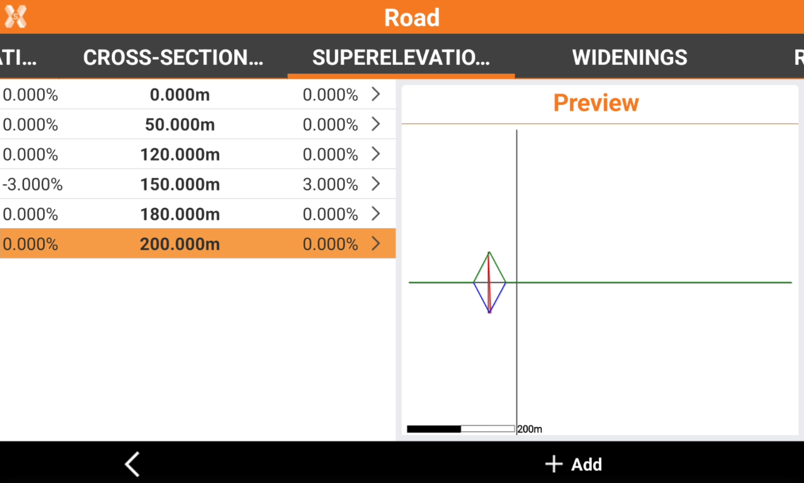
Click Add to add a new superelevation.
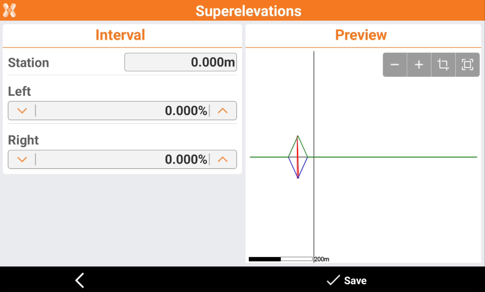
Station: chainage to which refer the values of superelevation.
Left: left superelevation.
Right: right superelevation.
Click Save.
The values of superelevation are interpolated and applied to the corresponding elements of the section model.
The calculated values for superelevation are applied only to those elements of the section model that are identified as items to rotate and enlarge.
Refer to Design a road step-by-step for more information on how to use superelevations to design cross sections.
Widenings
The page allows to specify widening values to use along the road axis.
This function is useful to add a widening to road elements when designing a road in the field.
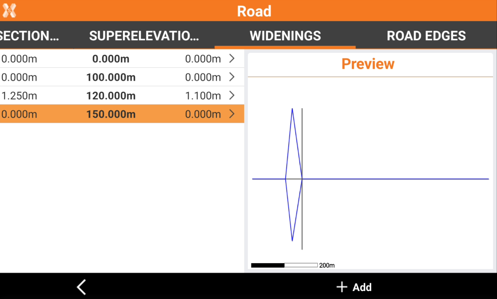
Click Add to add a new widening.
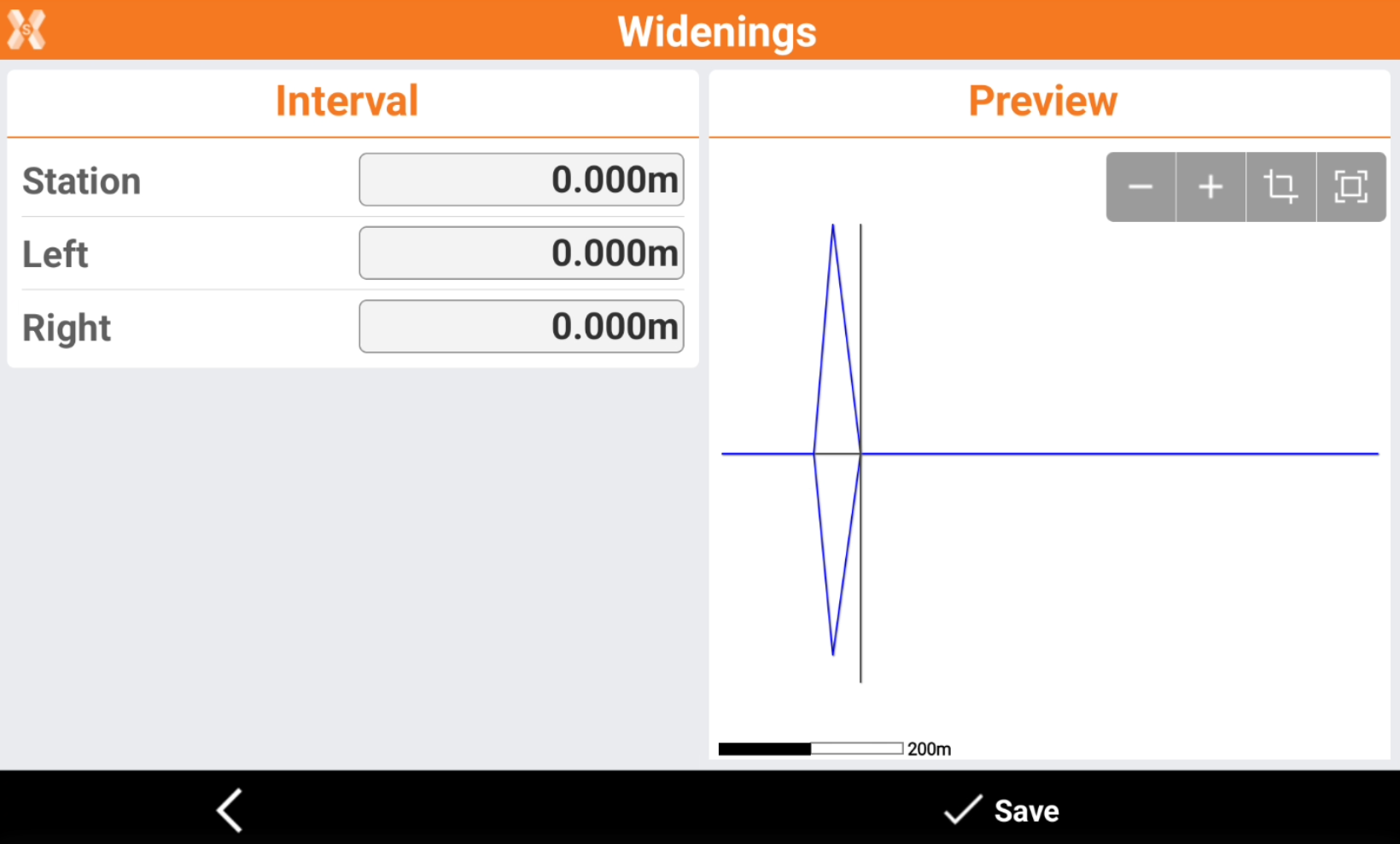
Station: chainage to which refer the values of widening.
Left: left widening.
Right: right widening.
Click Save.
The values of widening are interpolated and applied to the corresponding elements of the section model.
The calculated values for widening are applied only to those elements of the section model that are identified as items to rotate and enlarge.
Refer to Design a road step-by-step for more information on how to use widening to design cross sections.
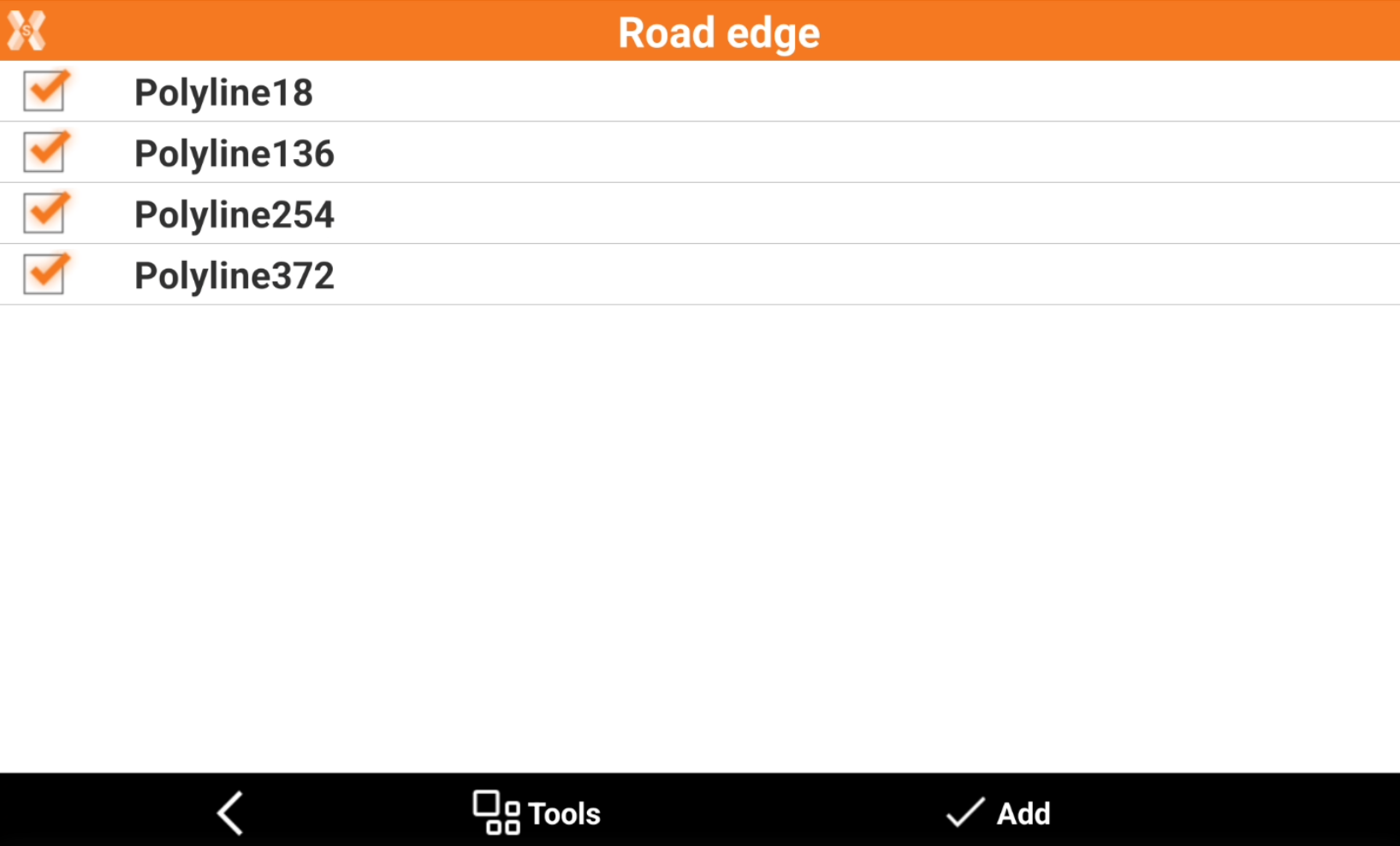
Road edges page
This page lists the road axis assigned as edges to the selected road.
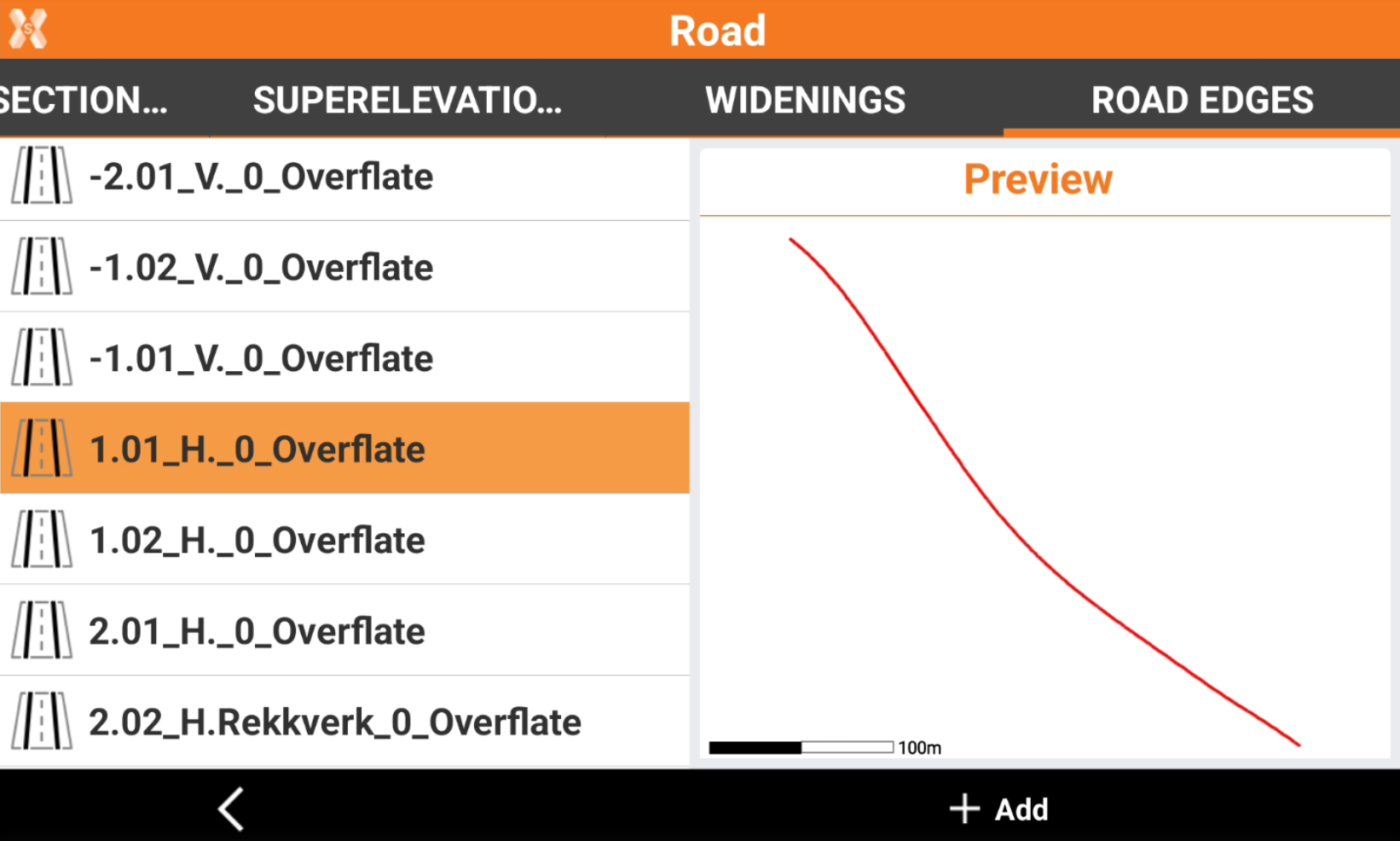
The page allows also to assign available road axis as edges to the selected road, for example when a road is imported from a DXF file.
Click Add to select available roads in Road Manager as road edges to the selected road.