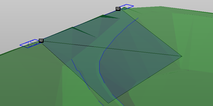
Generic cross sections are sections that can cut the model on a vertical, horizontal or sloped plane. Allows to create Horizontal, Vertical and By 3 points sections.
Add vertical cross section
The command inserts a new vertical section. This is inserted along one direction, it has a height that cut the model vertically.
-
Click Vertical.

-
Enter the base elevation or click on CAD to pick the base elevation
-
Select in CAD the starting and ending vertex of the cross section.
-
In CAD specify the height of the cross section.
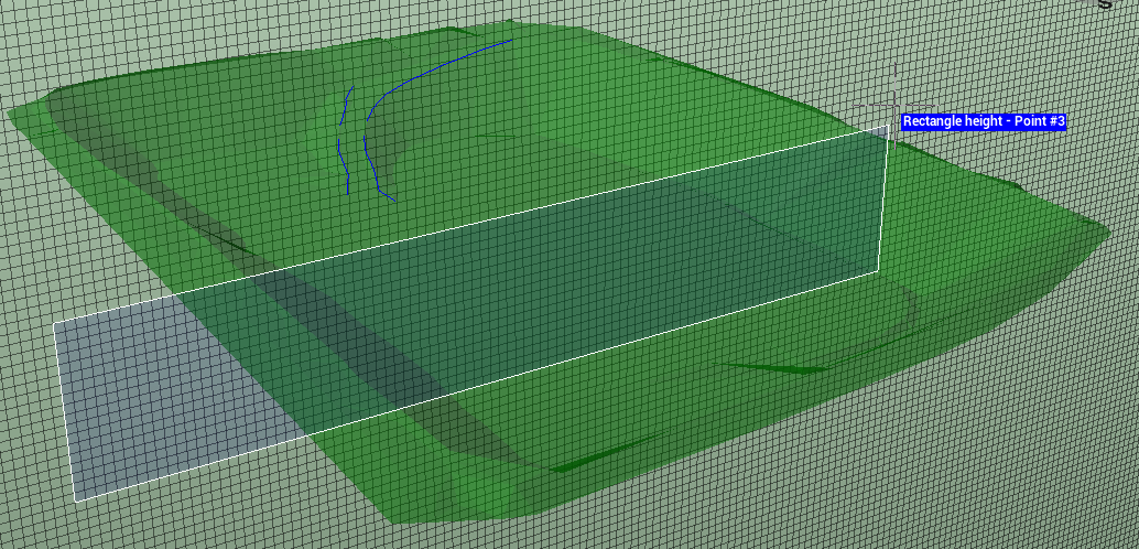
-
The cross section is created.
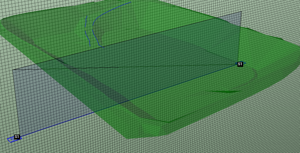
Add horizontal cross section
The command inserts a new horizontal section. This is inserted into a reference dimension and is defined by a rectangle that cut the model horizontally.
-
Click Horizontal.

-
Enter the reference elevation or click on CAD to pick the reference elevation
-
Select in CAD the base point and the height for the rectangle that cut the model.
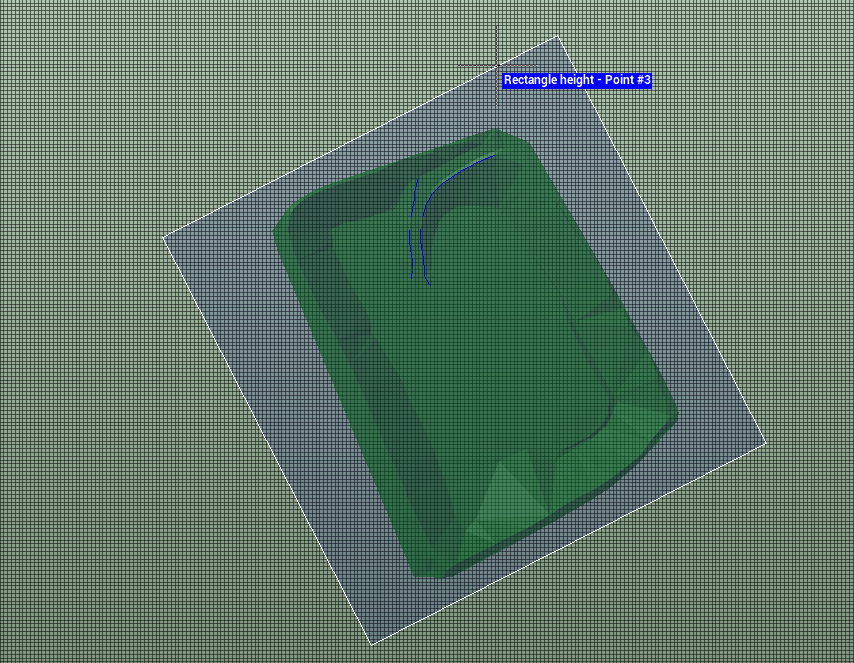
-
The cross section is created.
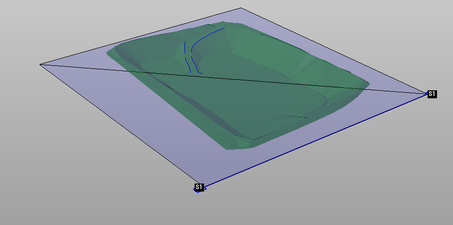
Add section by 3 points
The command inserts a new section as a 3-point pass plan. If points have different elevation the cross section will be on a slope plane.
-
Click By 3 points.

-
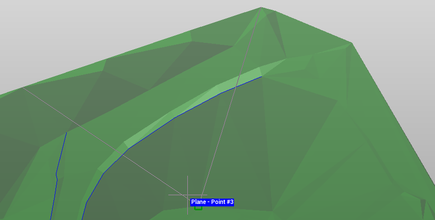
Select in CAD the three points that define the plane.
-
The cross section is created.