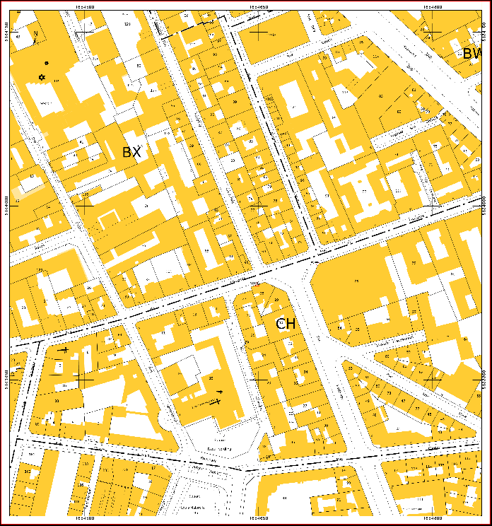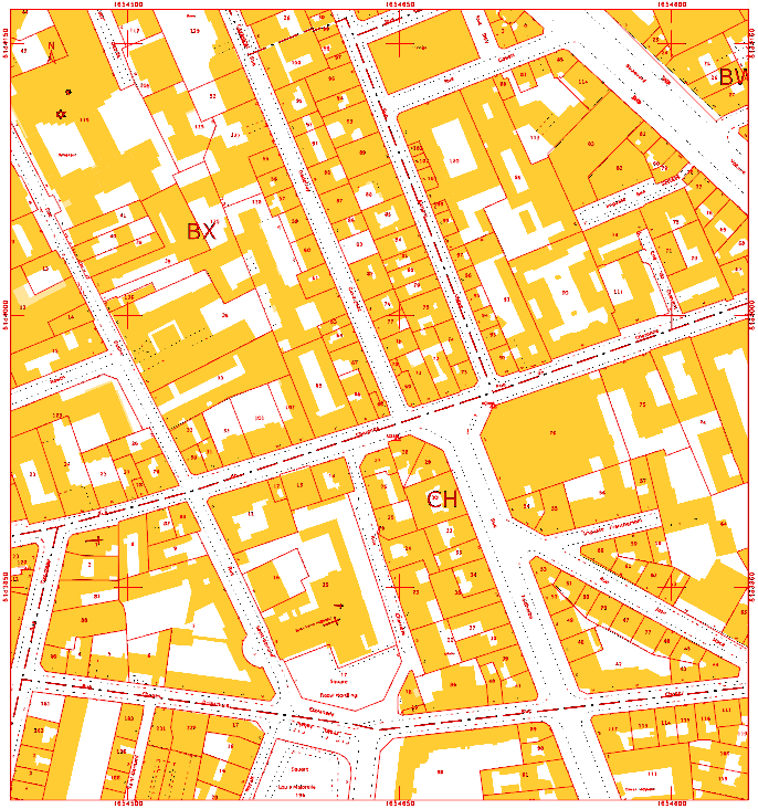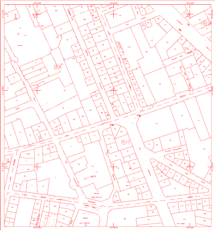
This command processes the Raster map and generate automatically vector elements (lines, arcs, circles).
-
Click Imaging.
-
With an available raster map in the Project Manager, click Vectorization.

-
The command opens a new panel on the right.
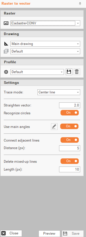
-
The different settings for vectorization are:
-
Raster: to select the Raster image you want to vectorize
-
Drawing: to choose the default Drawing and Layer for the vectorized elements.
-
Profile: select one of the three existing vectorization profiles. It is also possible to save or delete custom profiles.
-
Default.
-
Topography.
-
Engineering.
-
-
Trace mode: setting to determine how the software converts the raster image to vector shapes. There are 2 modes:
-
Outline: traces the outer edges or boundaries of shapes to create closed contours (useful when extracting the full shape of objects like buildings for example).
-
Centerline: traces the central axis of linear features, turning thick lines into single line vectors (helpful for line drawings like roads for example).
-
-
Straighten vector: determines the smoothness of the final vector (lower values for more details, higher values for smoother lines).
-
Recognize circles: identifies and converts circular shapes.
-
Use main angles: aligns vectors with common angles (e.g., 0°, 45°, 90°). Available if Trace mode is Center line.
-
Connect adjacent lines: links adjacent lines for continuity. Available if Trace mode is Center line.
-
Distance (px): selects the maximum distance between segments to consider them connected. Available if Trace mode is Center line.
-
Delete mixed-Up lines: deletes unnecessary overlapping line intersections. Available if Trace mode is Center line.
-
Length (px): selects the minimum line length to keep. Available if Trace mode is Center line.
-
-
When the different settings are selected, click Preview, to view the results of the vectorization before applying them.
-
When the result is satisfying, click Save button.