
-
Use the command Layout mode to create drawings (topographic points and lines) by defining directions and distances.
-
It is also possible to add arcs and specify elevations as absolute values, elevation differences, or slopes.
-
Click Draw.
-
Click below Polyline to open drop down menu.
-
Click Layout mode.

-
Click in CAD to define the starting point.
-
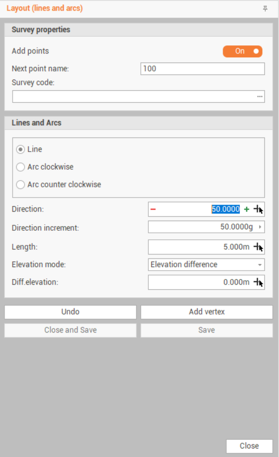
This function opens a table on the right side of the window.
-
Add points : enables the creation of topographic points. If disabled the software creates only lines and arcs.
-
Next point name: if Add points is enabled, defines the point name.
-
Survey code: if Add points is enabled, defines the survey code for the points.
-
-
Line: select Line to create a new line
-
Direction: the line direction. Click + and - to increase the angle by the value in Direction increment, or click

-
Direction increment: the direction increment to be applied in Direction.
-
Length: the line length. Click
-
Elevation mode: defines the elevation for the second point of the line.
-
Elevation difference: the elevation is calculated as elevation difference from the first point.
-
Absolute elevation: the elevation entered is the absolute elevation of the second point.
-
Slope: the elevation is calculated entering a slope value.
-
-
-
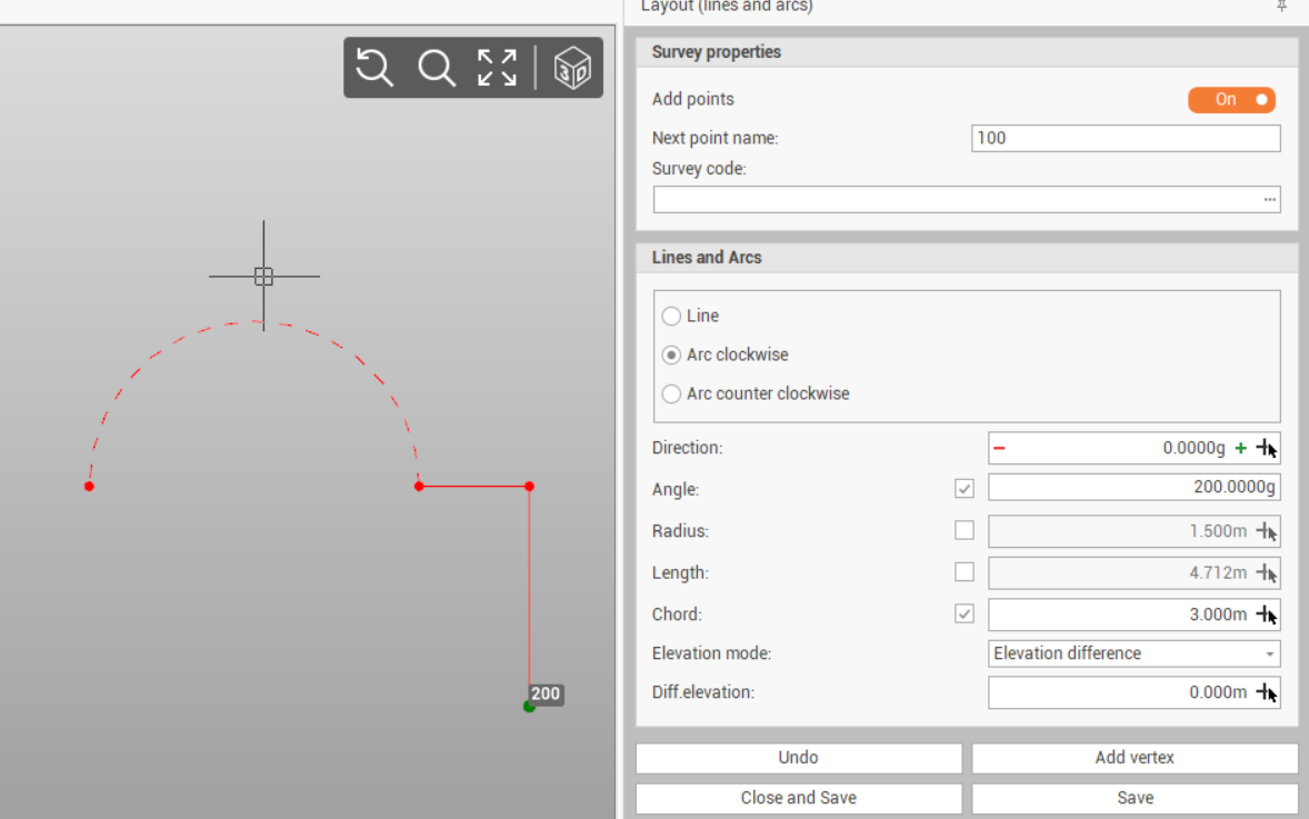
Arc: select Arc clockwise to create a new arc clockwise; select Arc counter clockwise o create a new arc counter clockwise. The arc can be defined by a combination of Angle, Radius, Length and Chord distance. Click

-
Direction: the arc starting direction. Click + and - to increase the angle by the value in Direction increment, or click
-
Angle: the angle of the arc.
-
Radius: the radius of the arc.
-
Length: the length of the arc.
-
Chord: the chord of the arc.
-
Elevation mode: defines the elevation for the second point of the line.
-
Elevation difference: the elevation is calculated as elevation difference from the first point.
-
Absolute elevation: the elevation entered is the absolute elevation of the second point.
-
Slope: the elevation is calculated entering a slope value.
-
-
-
Click Add vertex to add a new vertex to the polyline.
-
Click Undo to undo the last created vertex.
-
It is possible to use a combination of lines and arcs to create drawings.
-
Click Close and Save to close the polyline and save the lines and points.
-
Click Save to save the lines and points without closing the polyline.