

-
Calculate and stake out positions of the point of intersection of the project side slope with the existing terrain.
-
The stakeout position is calculated from the following information:
-
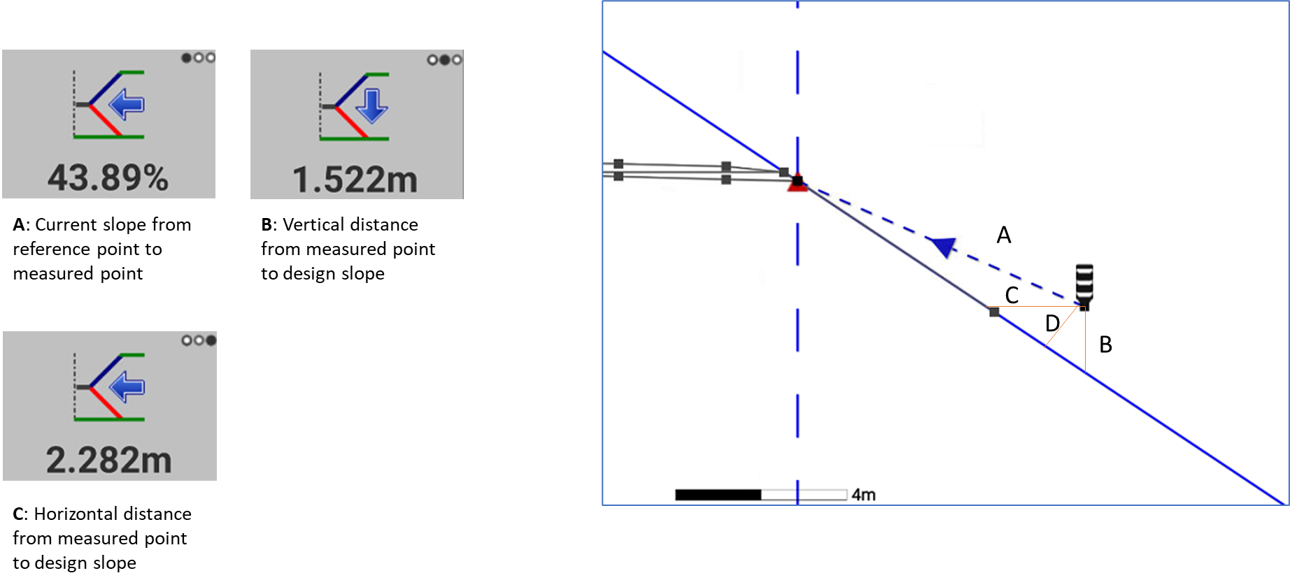
From the point position to the projection of the slope.
-
Distance to the stakeout element.
-
-
Click Stakeout.
-
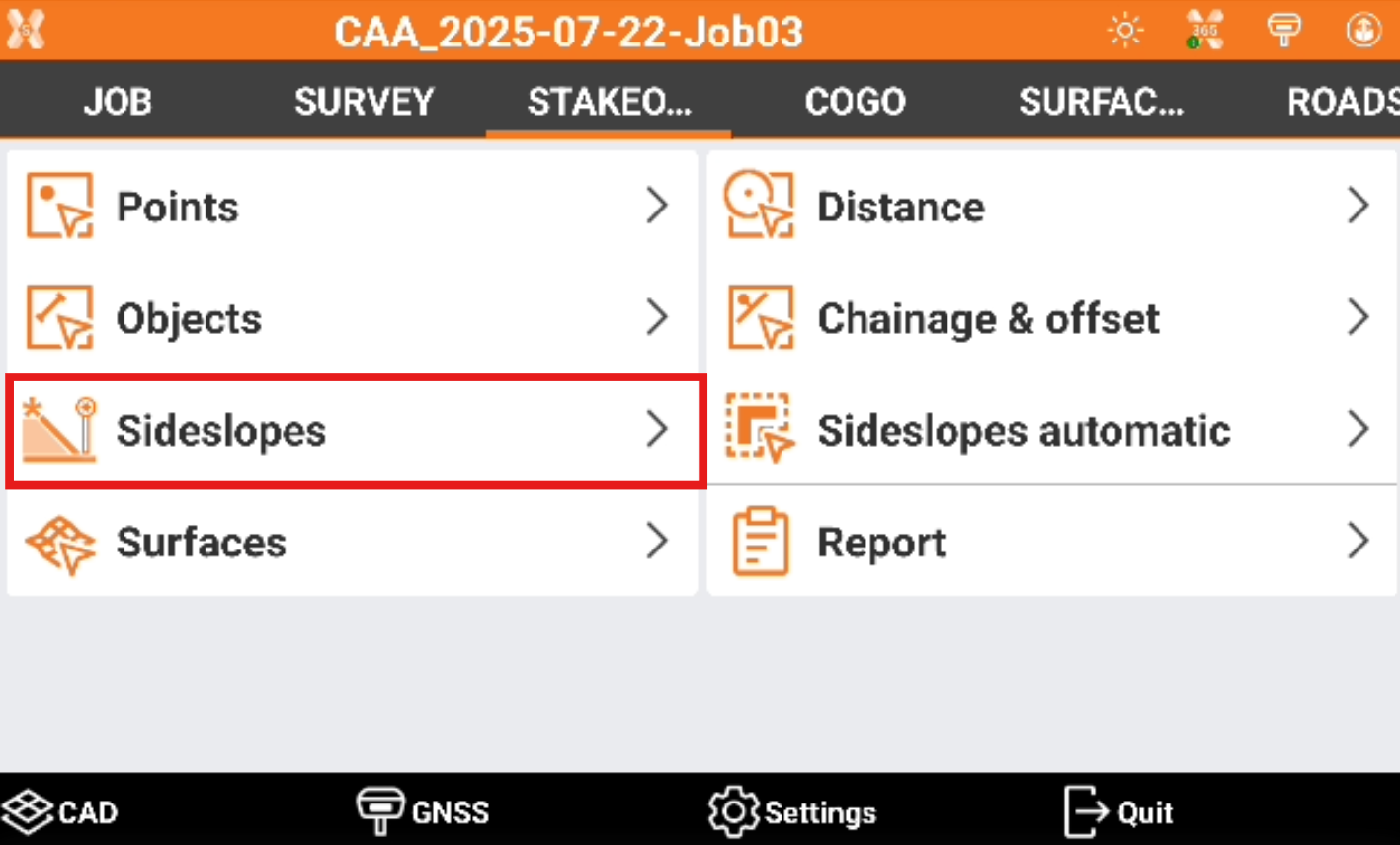
Click Sideslopes.
-
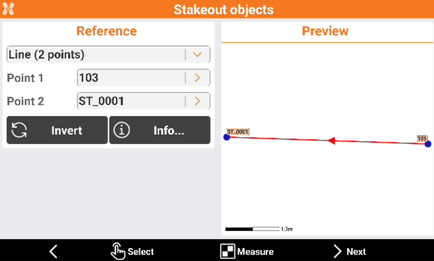
Select the horizontal alignment, from which the sideslope is defined.
-
Reference to stakeout.
-
Line (2 points): line defined by two topographic points. Requires to select Point 1 and Point 2.
-
Arc (3 points): arc defined by three topographic points. Requires to select Point 1, Point 2 and Point 3.
-
Arc (2 points+R): arc defined by two topographic points and by the radius. Requires to select Point 1, Point 2 and arc radius.
-
Drawing object: select a line, polyline, arc or circle in the graphic window. This option allows for example to stakeout a drawing element imported.
-
-
-
Click Invert to invert the reference direction.
-
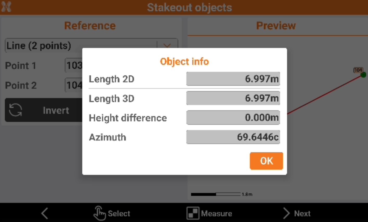
Click Info to have information on the reference object.
-
Click Select to pick the points directly from CAD or click Measure to measure the reference points.
-
After the reference object has been selected click Next to define the parameters.
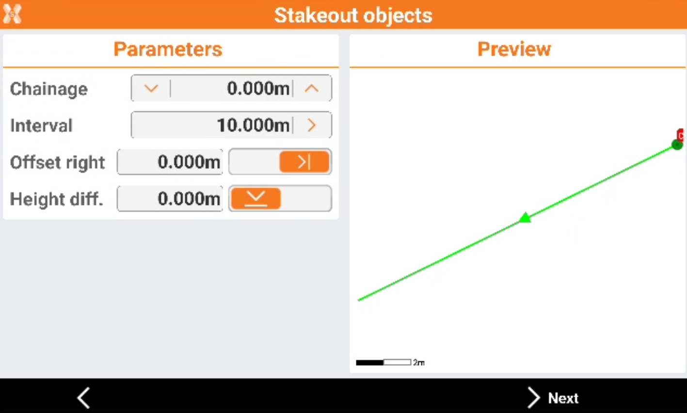
-
Chainage: distance on the reference element on which is the position to reach on the horizontal alignment from where the sideslope starts.
-
Interval: distance between the points along the reference element. Use the button on the right to calculate the interval dividing the length of the reference element in a defined number of parts.
-
Offset: distance perpendicular to the reference element. Use the button on the right to define if the sideslope is on the left or right side of the reference element.
-
Height diff.: elevation difference to apply to the calculated point. The software interpolates the elevation on the reference element with the defined station distance. A slope can be added to the interpolated elevation.
-
-
Click Next to define the slopes.
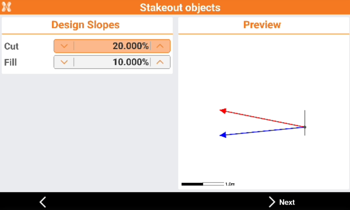
-
In this page we define the slope value in the cut or fill condition.
-
Cut: slope value in the cut condition (receiver elevation above the starting elevation of the slope).
-
Fill: slope value in the fill condition (receiver elevation under the starting elevation of the slope).
-
-
Tap Next to start staking out of the calculated position.
-
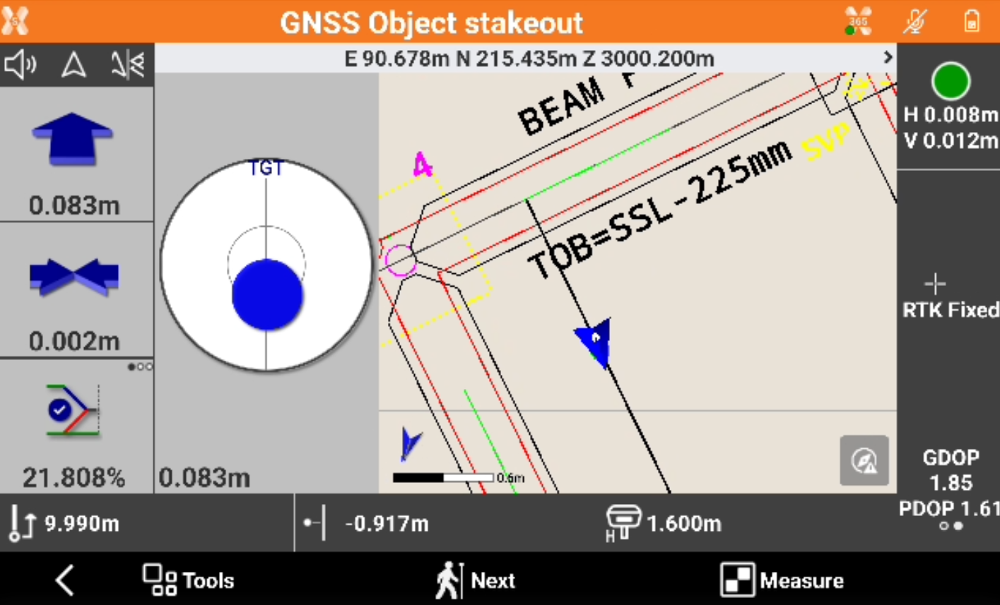
After having defined the reference element, the offset parameters and slopes, the main stakeout window appears.
-
In addition to the visualization mode described in previous paragraphs, this graphical view contains the cross section of the side slope and current position.
-
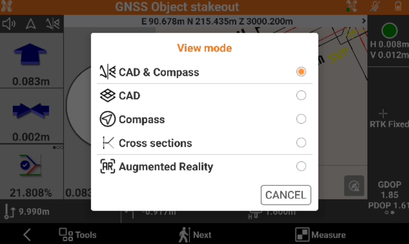
Click View mode and select Cross sections.
-
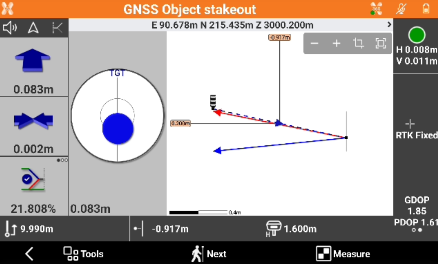
This view shows the current cross section with the instrument position and the cut/fill design slopes.
-
The side panel contains the information to get the point of intersection.
-
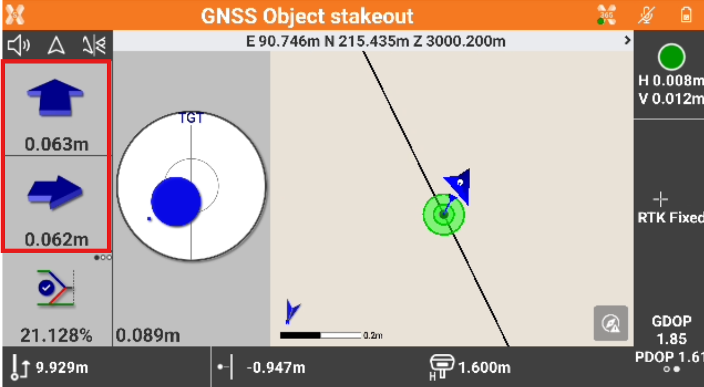
The side panel contains the information to get the point of intersection.
-
First value refers to the vertical distance from the position to side slope. Second value refers to the horizontal distance from the position to side slope.
-
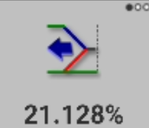
Third value shows the current value of the slope.
-
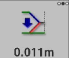
Click to display the cut/fill value to achieve the project slope value.
-
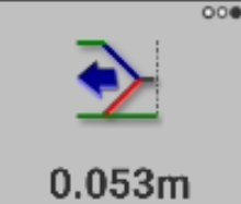
Click again to display the perpendicular distance to the point to achieve the project slope value.
-
A scheme of the information is visualized in the picture below.