Sections and profile management
After the calculation the cross sections lines are created in the CAD view. Click Cross section to open the cross section view.

This function opens a window with the cross section view.
Section display properties
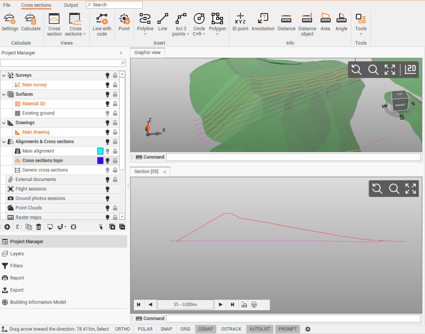
In the graphic view, the cross section is visualized as polyline on the 3D model.
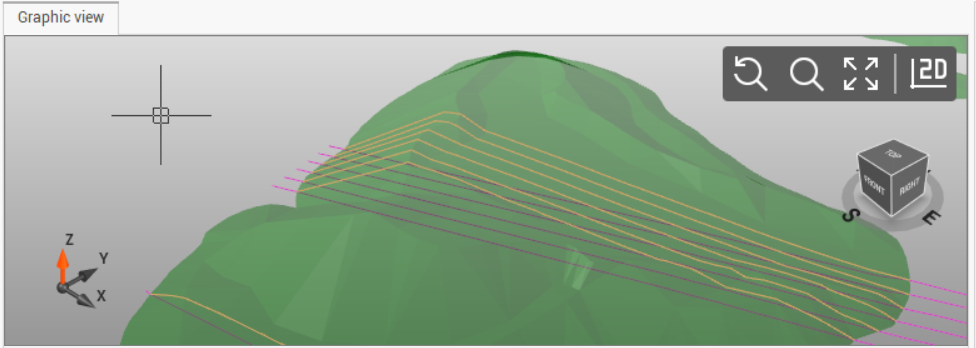
In the cross section view, the cross section is visualized as front view.
The cursor is connected between the two views; when you move the mouse along the cross section in the cross section view, the cursor follows the cross section in the graphic view.
In the cross section view click on the arrows to change between the different cross sections.

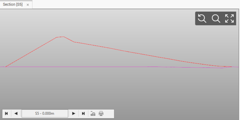
Click on Layout mode icon to change to layout view.

The Layout mode shows the cross section as will be plotted. The layout can be configured in the settings (see Group of sections layout styles ).
Cross sections toolbar
The cross sections toolbar is available when the cross section view is opened and selected.
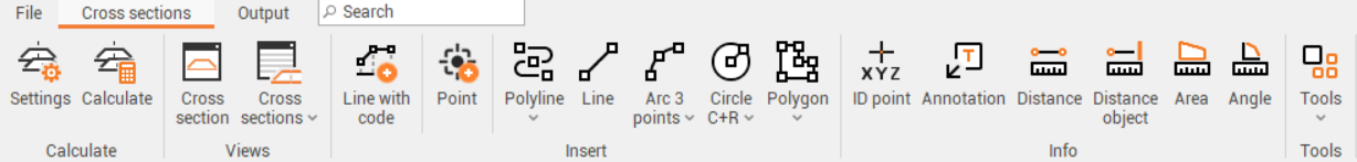
It has the following commands:
Settings: shows the Settings window (see Group of sections settings).
Calculate: calculates all the sections with the rules set.
Cross section: opens a new cross section view panel.
Cross sections: opens the cross sections table.
Line with code: allows to create a line in the cross section view using the line codes defined for the cross section. After selecting the function you can select in the bottom bar the line code to use.
Point: adds a new topographic point from the cross section.
Polyline: draws a polyline in the cross section view (see Polyline commands).
Line: draws a line in the cross section view (see Line).
Arc: draws an arc in the cross section view (see Arc).
Circle: draws a cyrcle in the cross section view (see Circle).
Polygon: draws a polygon in the cross section view (see Polygon).
ID point: creates a point ID label in the cross section view (see ID point).
Annotation: inserts a free annotation in the cross section view (see Annotation).
Distance: calculates a distance between points and enter an annotation in the cross section view (see Distance).
Distance object: calculates distnance from a point and a drawing object and enter an annotation in the cross section view (see Distance object).
Area: calculates an area and enter an annotation in the cross section view (see Area).
Angle: calculates an angle and enter an annotation in the cross section view (see Angle).
Tools: opens the cross sections tools:
Topographic points from cross sections: to generate topographic points from the vertices of the cross sections (see Cross sections tools).
Delete cross section lines: allows to delete cross section lines from a selection of cross sections (see Cross sections tools).
Output toolbar
The Output toolbar commands allow several operations including the settings for plotting and exporting to external CAD.
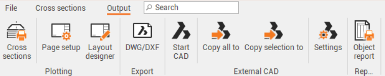
The output toolbar has the following commands:
Cross-sections: opens the plot preview of the cross section (see Plot boxes).
Page setup: allows to define the page setup and properties for the plot (see Page setup).
Layout designer: opens a designer tool to edit or define new plotbox layout (see Layout designer).
DWG/DXF: exports cross section layout to AutoCAD DWG or DXF format. (see Export drawing in DWG/DXF format for AutoCAD).
Start CAD: starts configured external CAD software (see AutoCAD/BricsCAD connection).
Copy all to: copies all visible drawings to the clipboard and paste them directly to the opened CAD window (see AutoCAD/BricsCAD connection).
Copy selection to: copies selected objects to the clipboard and paste them to the opened CAD window (see AutoCAD/BricsCAD connection).
Settings: opens a windows to define the CAD external software and the parameters of the connection (see AutoCAD/BricsCAD connection).
Object report: generates a report with coordinates of selected drawing elements (see Object report).