


-
The Check planes function allows to check drawing elements or measured positions on site.
-
The function allows to check horizontal, vertical and sloped planes.
-
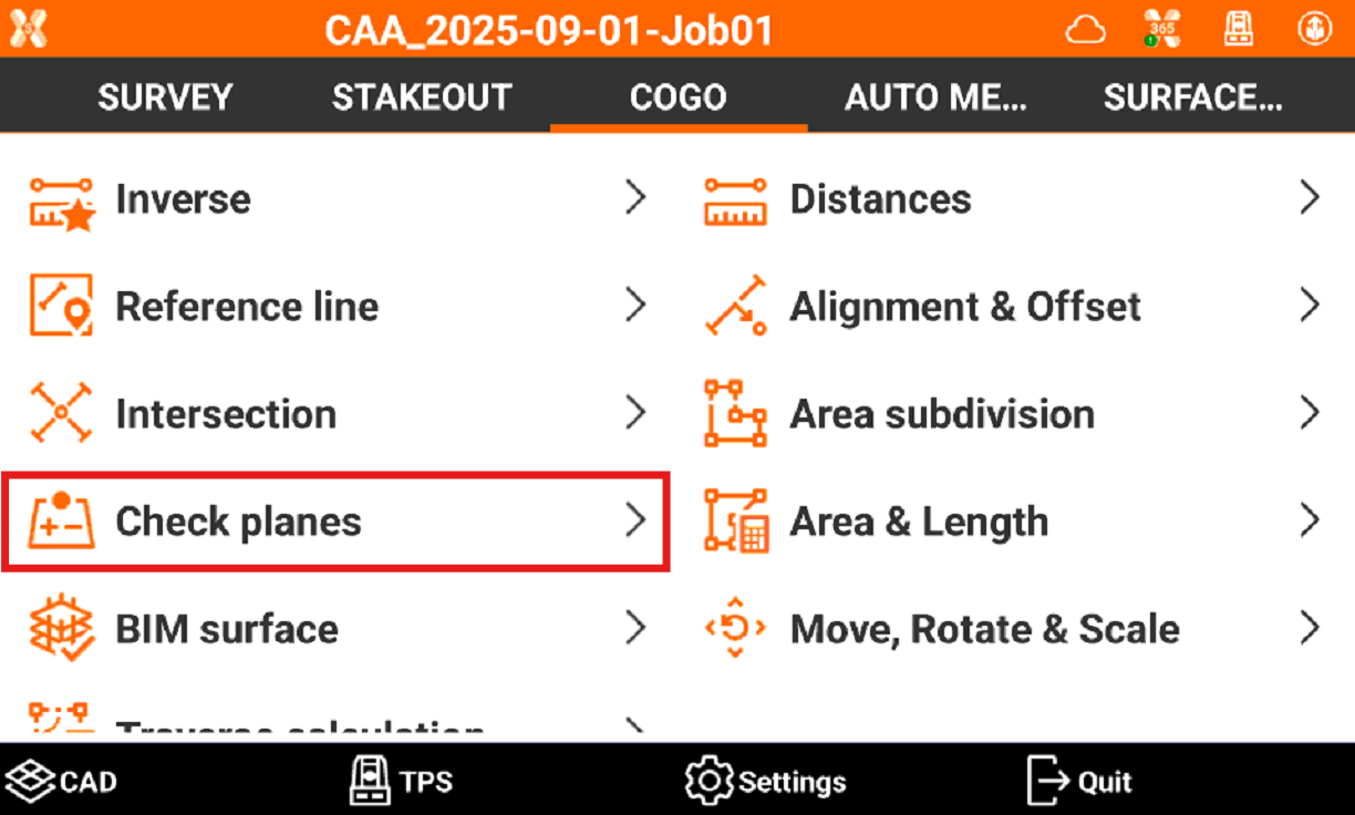
Click COGO.
-
Select Check planes.
-
Select the mode to use:
-
Horizontal level: checks the elevation difference between the reference elevation and the elevation measured by the instrument. The software uses a horizontal level passing through the reference elevation to perform the control.
-
Vertical plane: available for TPS instruments. Checks the elevation difference between the reference elevation and the elevation measured by the instrument. The software uses a vertical level passing through the reference points.
-
Level with 1 slope: checks the elevation difference between a defined level by applying a gradient along a reference direction and the current measured elevation.
-
Level with 2 slopes: checks the elevation difference between a defined level and the elevation measured by instrument. A reference plane is defined by applying a first slope on a reference axis and a second slope on the axis perpendicular to it.
-
Level by 3 points: checks the elevation difference between a reference level and the measured current elevation. The reference level is defined by measuring three references points.
-
Check horizontal level
-
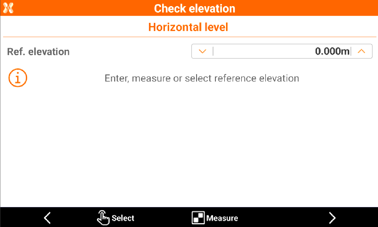
Select Horizontal level as mode.
-
Ref. elevation: sets the reference elevation to use for the elevation check.
-
-
Click Select to select the reference elevation from CAD.
-
Click Measure to measure with current instrument the reference elevation.
-
Click Next to proceed.
-
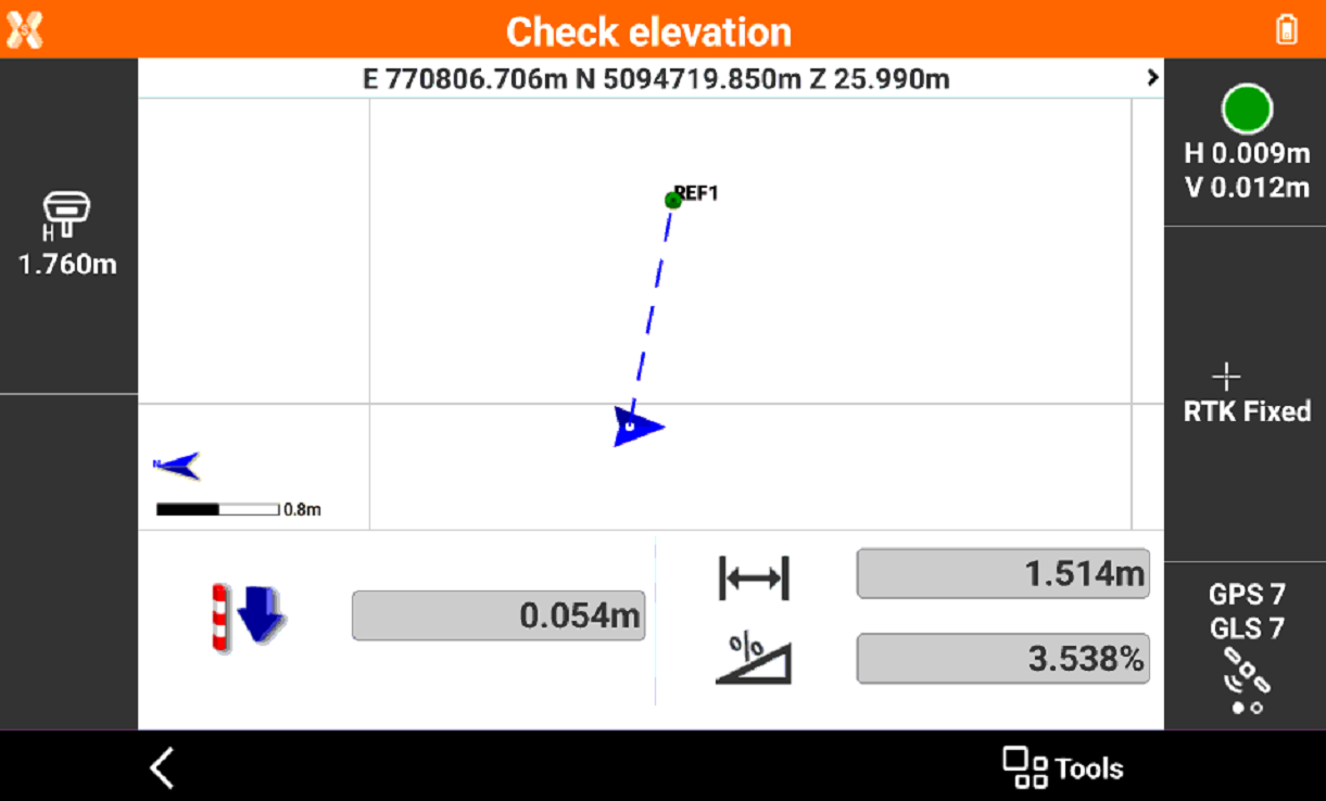
The software displays in real time:
-
Difference between the measured elevation and the reference elevation.
-
Distance between the reference point and the current position.
-
Slope between the reference point and the current position.
-
Check vertical plane (TPS Only)
-
Select Vertical plane as mode. This mode is only available when working with a total station.
-
Measure or select the points that define the origin of the vertical axis and the direction of the vertical axis.
-
Click Select to select the reference elevation from CAD.
-
Click Measure to measure with current instrument the reference elevation.
-
Click Next to proceed.
-
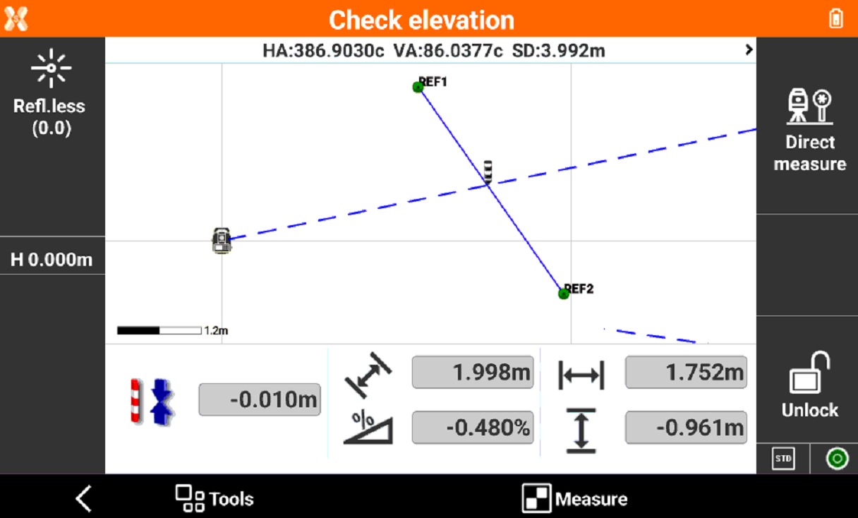
The software displays in real time:
-
Difference in distance projected to the vertical plane between the measured point and the reference plane.
-
Distance between the reference point and the current position.
-
Slope between the reference point and the current position.
-
Check level with 1 slope
-
Select Level with 1 slope.
-
Measure or select the origin of the axis and the direction of the axis.
-
Enter the slope value.
-
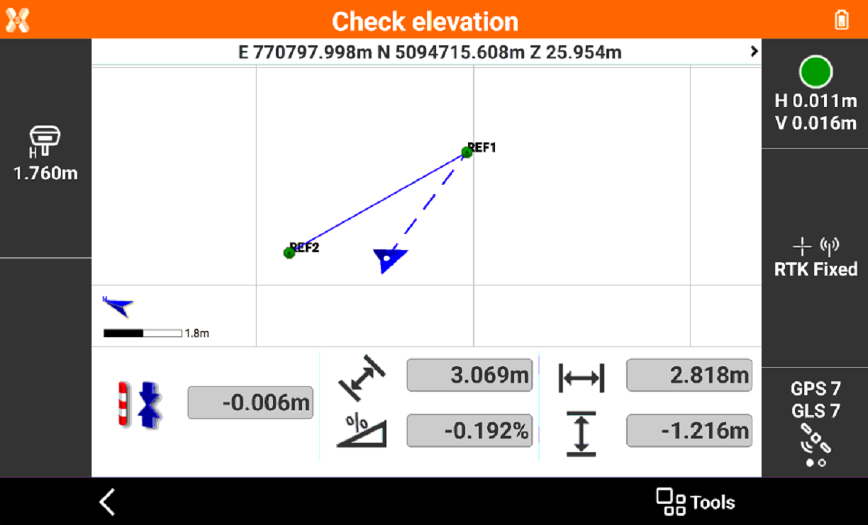
Displayed is in real time:
-
Difference between the measured elevation and the reference elevation.
-
Distance between the origin and the reference line.
-
Current slope.
-
Check level with 2 slopes
-
Select Level with 2 slopes.
-
Measure or select the origin of the axis and the direction of the axis.
-
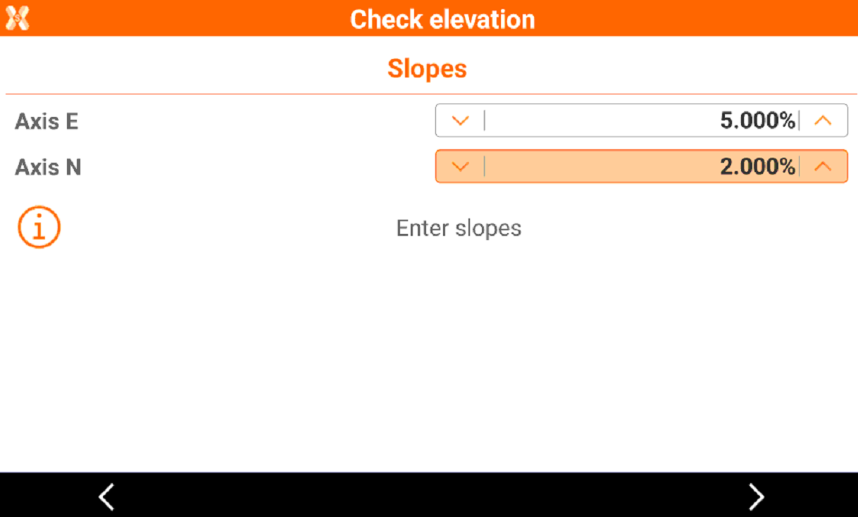
Enter the slope values on the two axis.
-
Click Next to proceed.
-
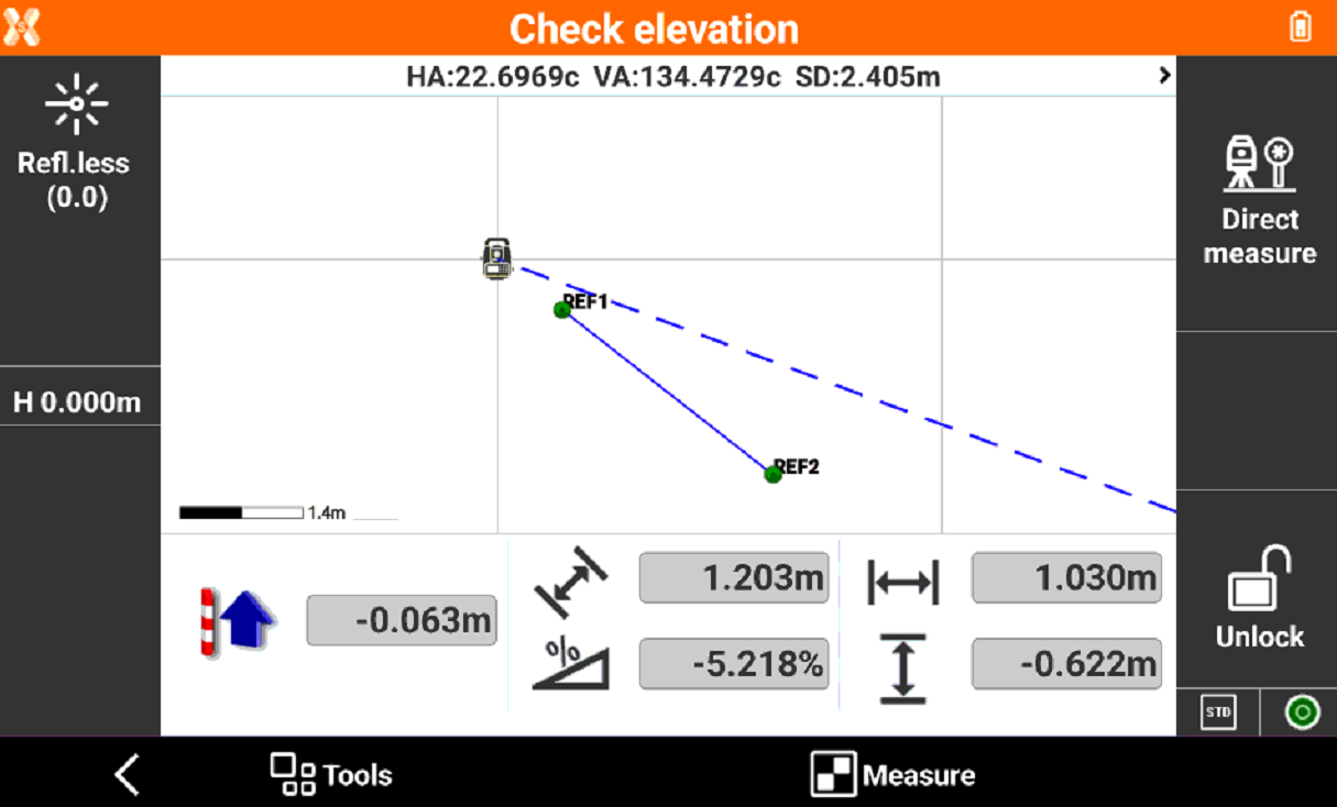
Displayed is in real time:
-
Difference between the measured elevation and the reference elevation.
-
Distance between the origin and the reference line.
-
Current slope.
-
Check level by 3 points
-
Select Level by 3 points.
-
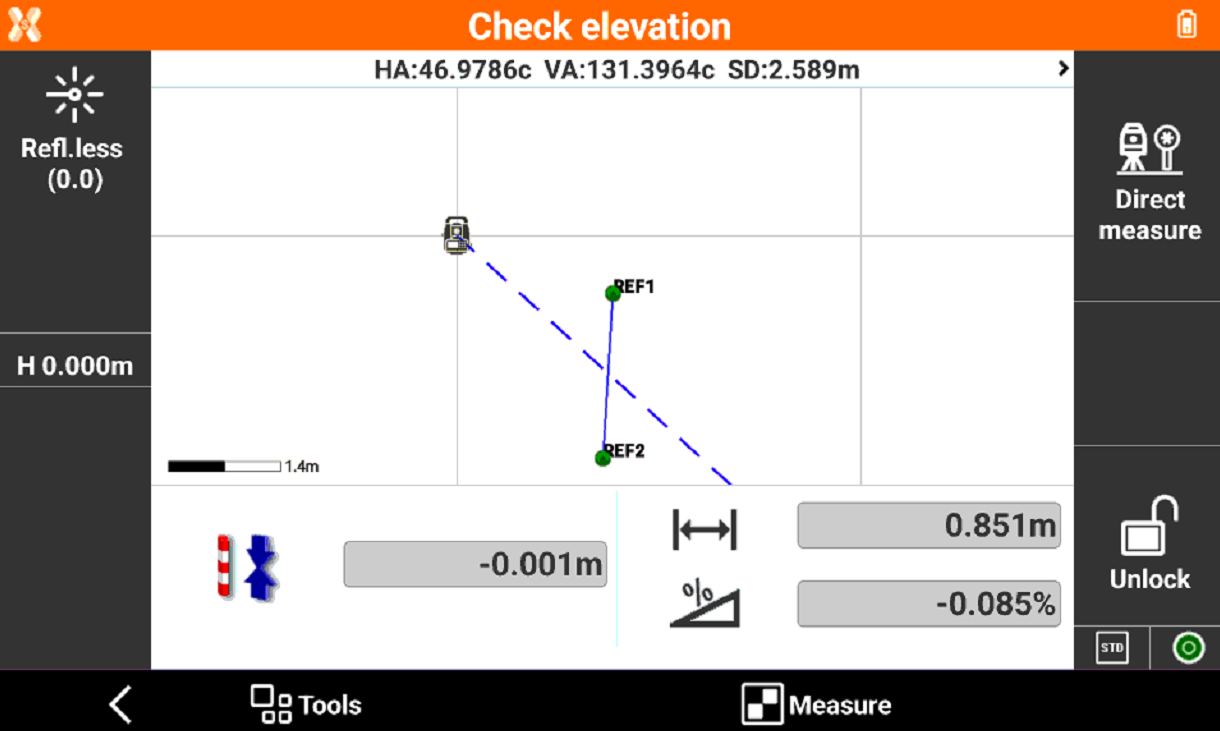
Measure or select the three reference points that will define the sloped plane.
-
The software displays in real time:
-
Difference between the measured elevation and the reference elevation.
-
Distance between the reference point and the current position.
-
Slope between the reference point and the current position.
-