


-
The function Where am I? provides information about the current position in relation to the selected road project (road design) or a a 3D surface.
-
The function allows to stakeout the road design data without the need to specify a station and an offset.
-
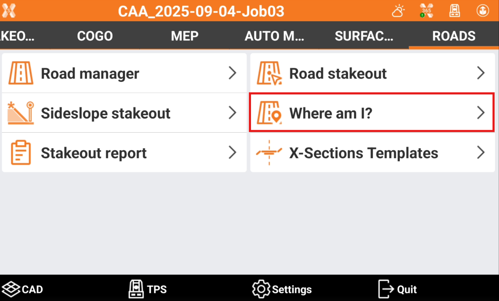
Click Roads.
-
Click Where am I?.
-
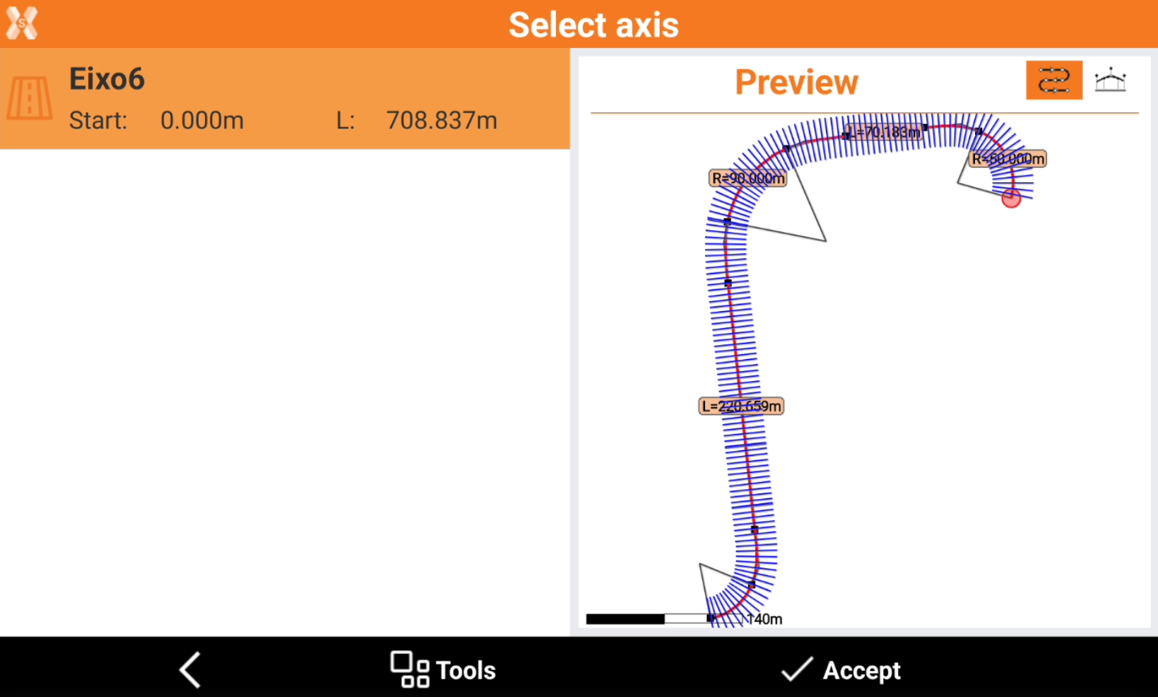
Select the road to stakeout.
-
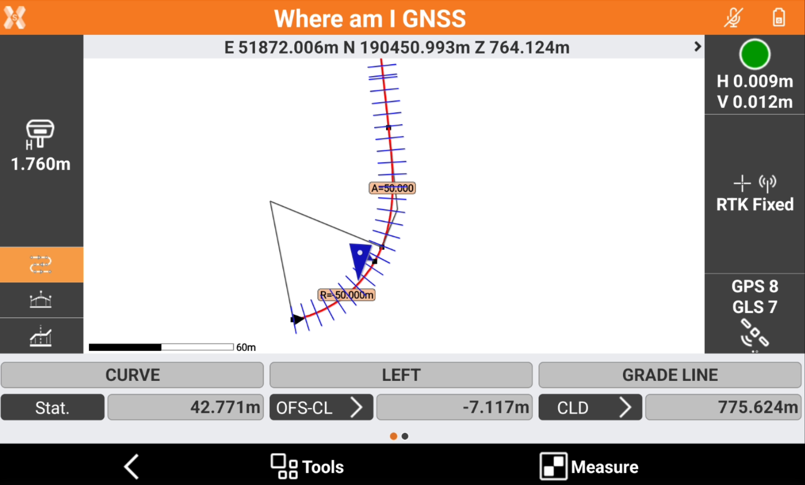
The software shows the current target position in relation to the road design.
-
Based on the position, the following information are displayed.
-
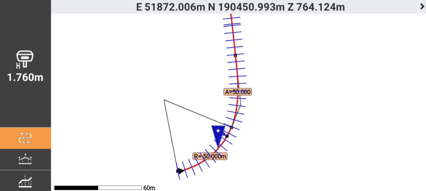
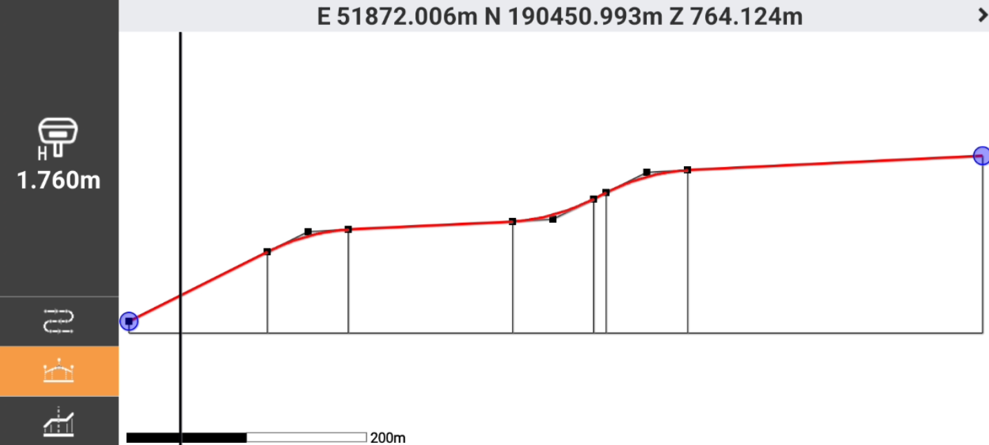
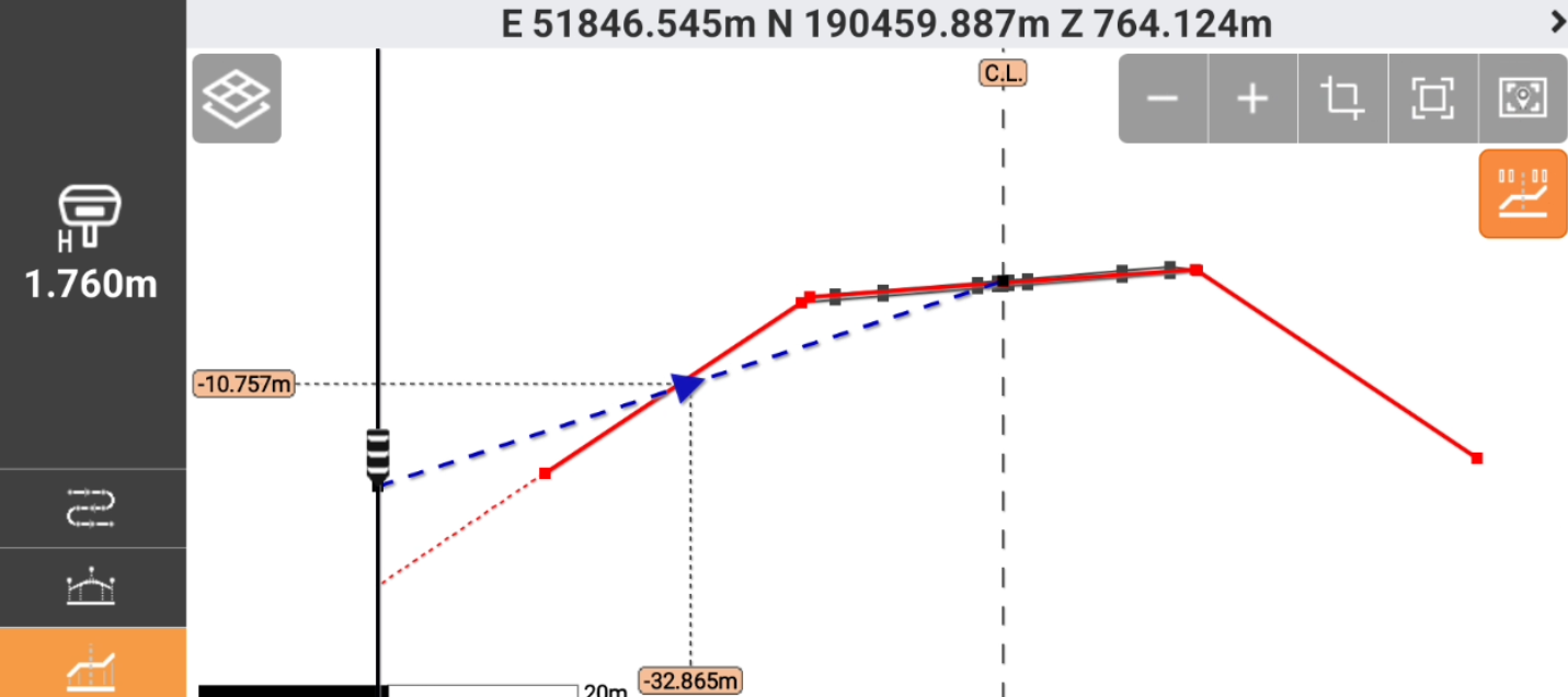
Graphically visualization of the current position as plan view, profile view and cross section view.
-
Chainage of the current position.
-
Distance from the reference axis or a selected axis.
-
Element of the horizontal alignment.
-
Element of the vertical alignment.
-
Absolute elevation, axis elevation, elevation difference from the design.
-
Right or left side of the track.
-
Where am I? toolbar
-
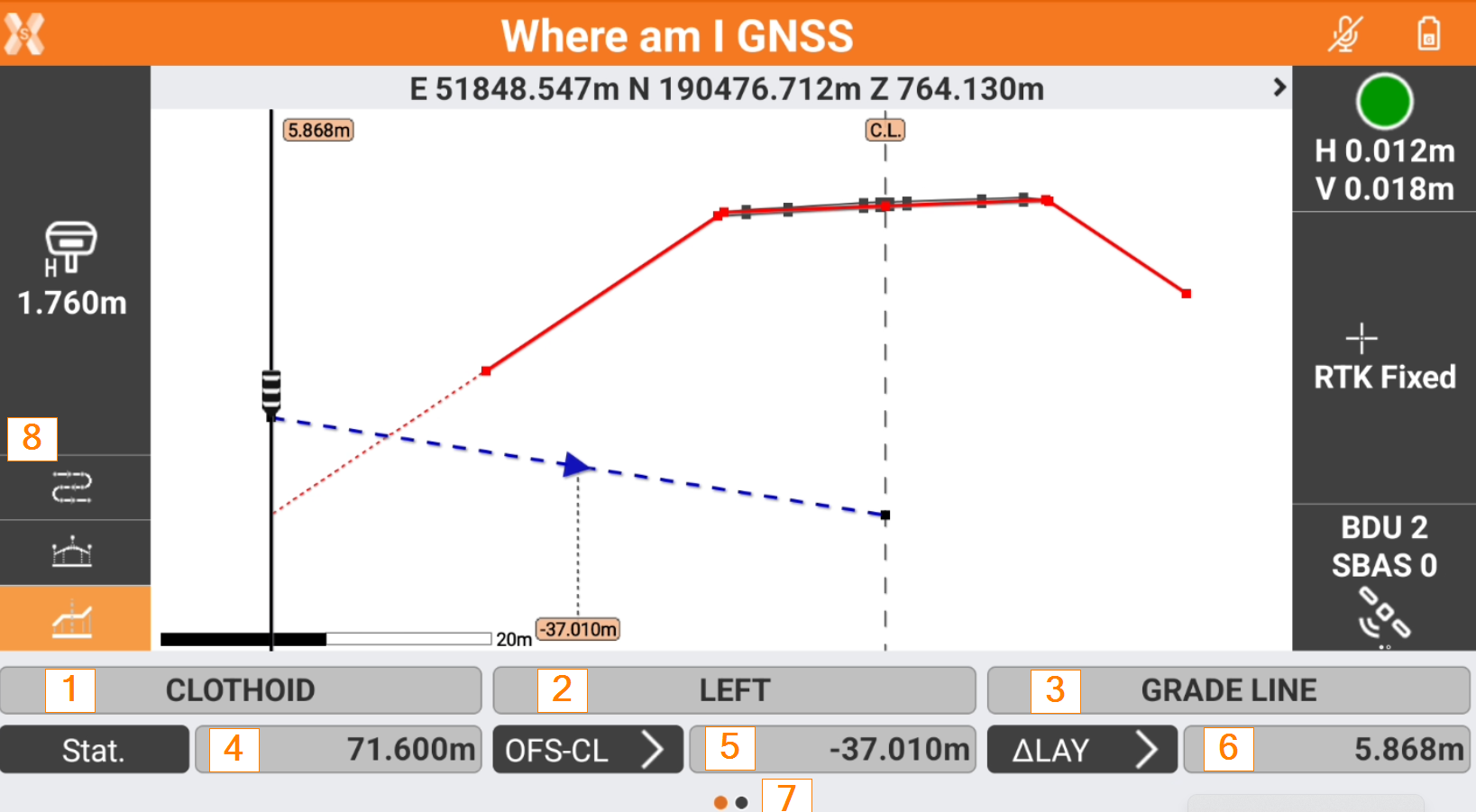
The bar shows different information related to the road design.
-
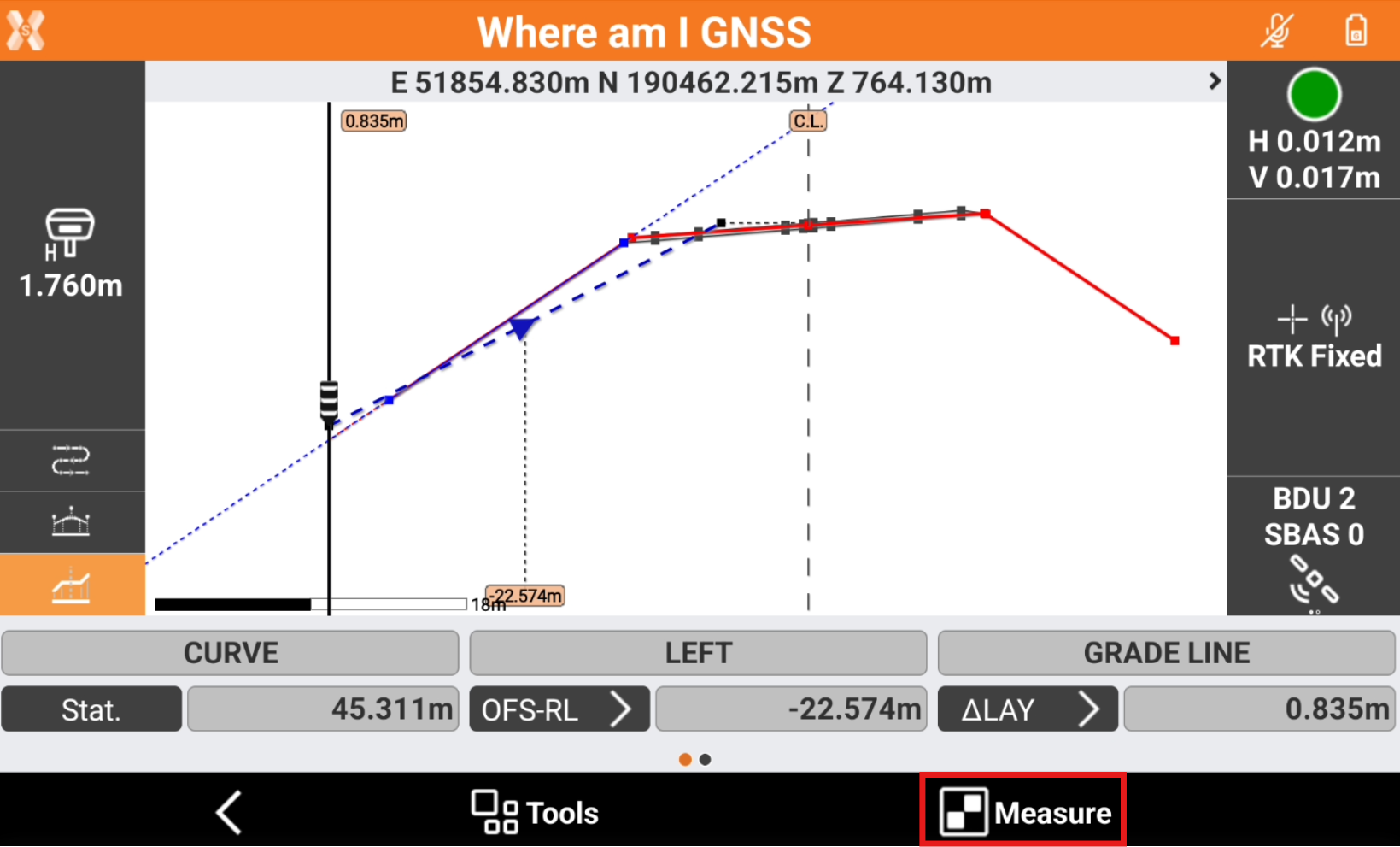
1: the element of the horizontal alignment at the current position.
-
2: shows if the current position is on the left or right side of the road.
-
3: the element of the vertical alignment at the current position.
-
4: current station.
-
5: horizontal offset from the reference element. Clicking the button it is possible to change the Offset mode.
-
6: difference elevation. Clicking the button it is possible to change the Elevation mode.
-
7: scroll the toolbar on the right to open the tools page.
-
8: change the view mode.
-
Change the view mode
-
On the left bar it is possible to change the view mode.
-

-

-

-
Offset value and offset mode
-
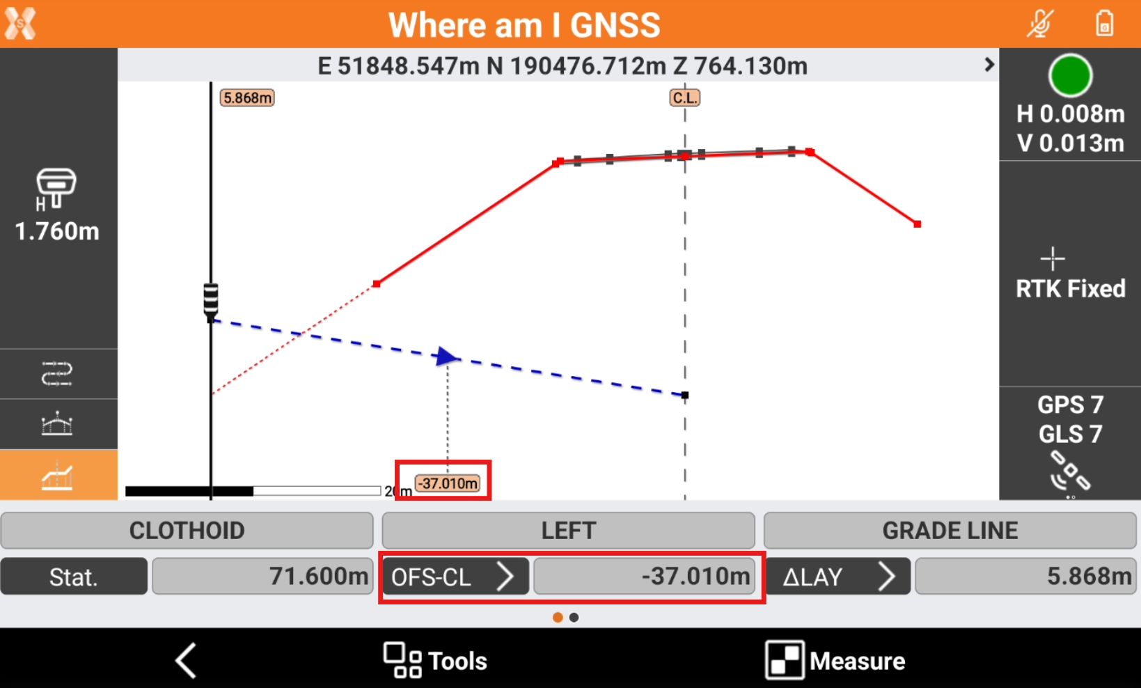
The function allows to stakeout the horizontal offset from the centerline or from a reference axis.
-
The information regarding the offset is available in the toolbar and on the graphic view when in cross section view.
-
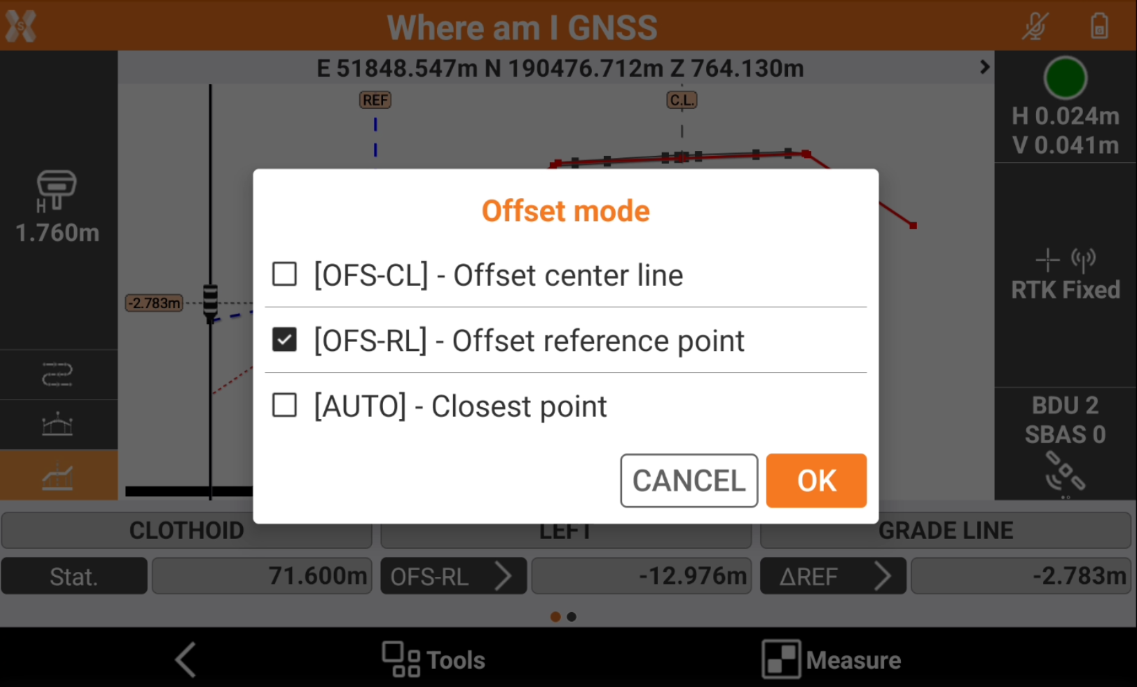
Clicking on the offset button in the toolbar it is possible to change the Offset mode.
-
OFS-CL: the offset value is referred to the center line.
-
OFS-RL: the offset value is referred to the selected reference point. A reference point has to be selected.
-
AUTO: the software shows the offset automatically referring to the closest axis.
-
-
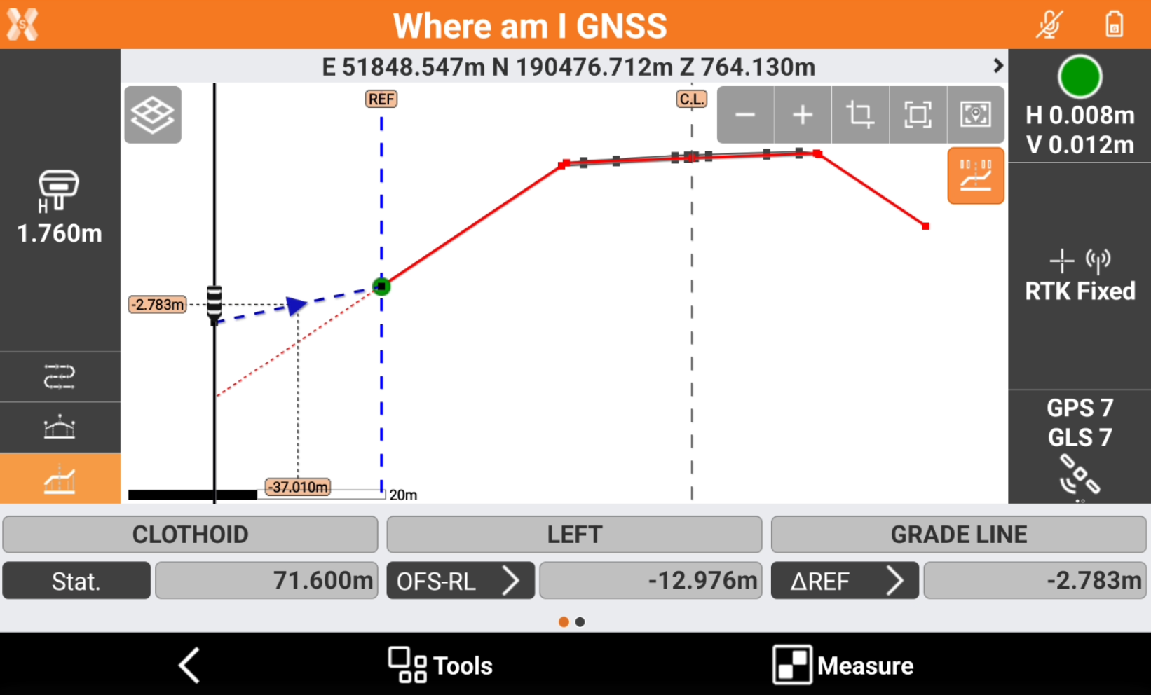
It is possible to select or change the reference point, for example when it is required to stakeout a different axis, clicking in the cross section view at a different vertex to change axis.
-
The offset is now to the selected reference point.
-
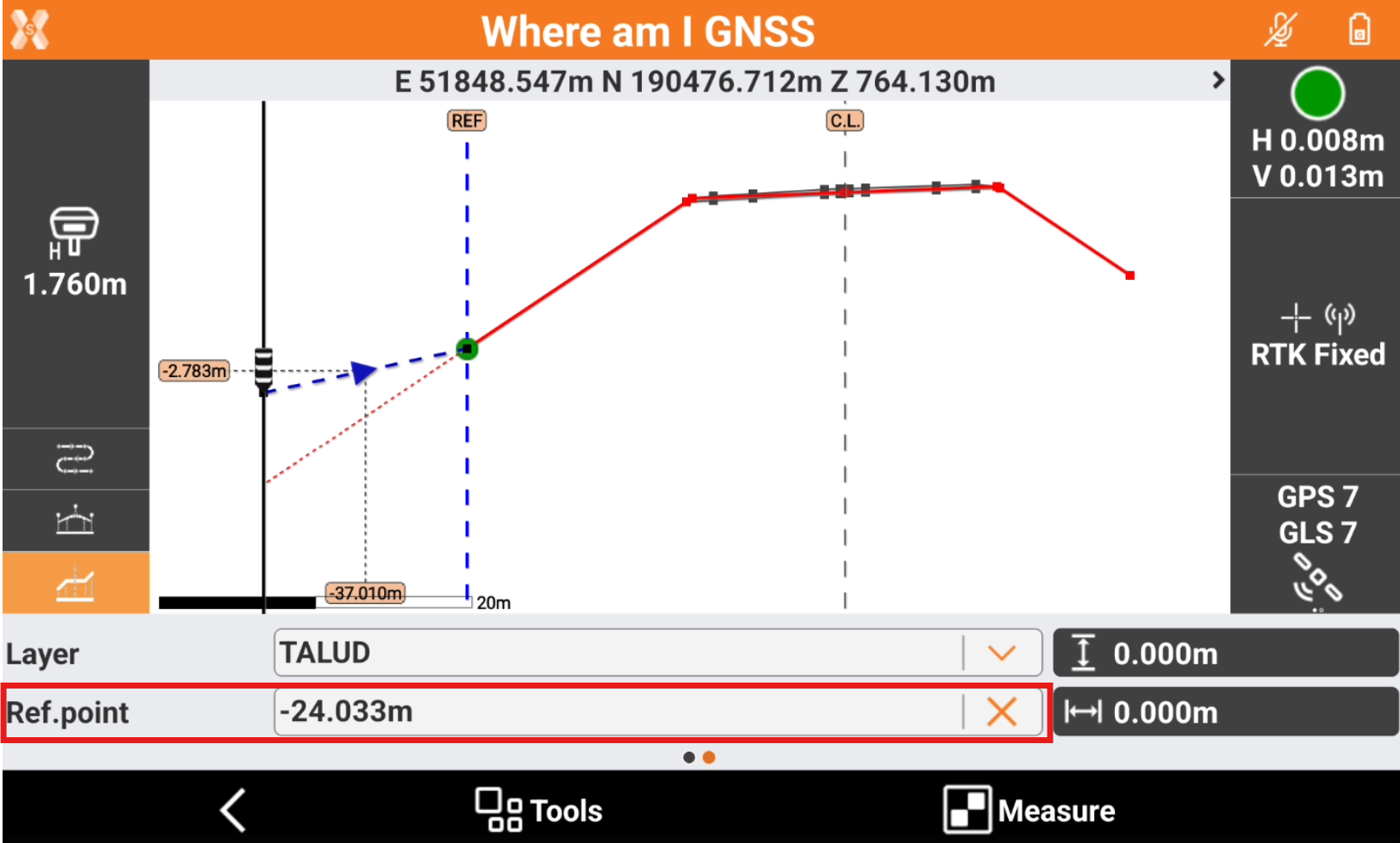
The selected reference point is visualized graphically with the label REF and the offset of the reference point is visible scrolling the toolbar on the right, as Ref.point.
-
Click X to remove the current reference point or click to a different reference point in the cross section view to select a different one.
-
Below video shows how to change from centerline, to a reference axis and use the Offset mode commands.
Elevation difference and elevation mode
-
The function allows to stakeout the cross section and show the difference elevation to the design, to a reference point or to the centerline.
-
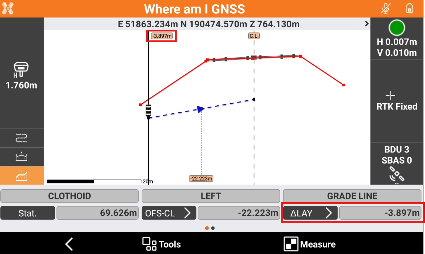
The information regarding the different elevation is available in the toolbar and on the graphic view when in cross section view.
-
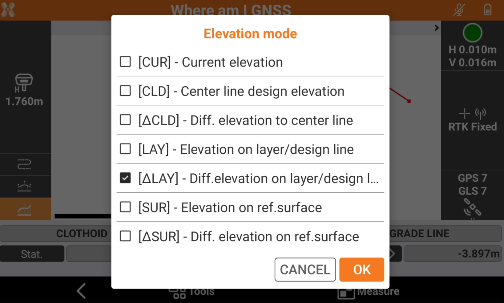
The field shows the different elevation related to different road design elements. Click on the button to change the Elevation mode.
-
CUR: the current instrument elevation.
-
CLD: the elevation of the center line at the current station.
-
∆CLD: the different elevation from the current position to the center line at the current station.
-
LAY: the elevation of the cross section at the current position.
-
∆LAY: the different elevation from the current position to the design cross section.
-
SUR: the elevation of the reference surface at the current position. Requires a reference surface to be loaded in Tools.
-
∆SUR: the different elevation from the current position to the reference surface. Requires a reference surface to be loaded in Tools.
-
-
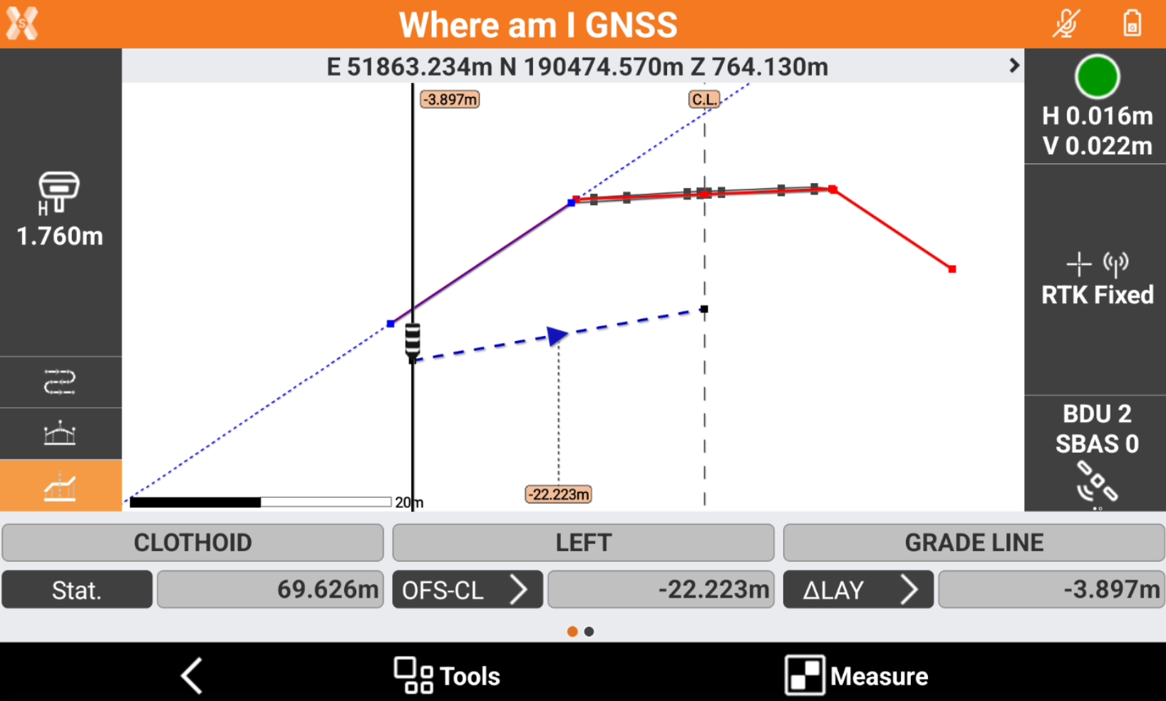
It is possible to select a cross section segment to stakeout clicking in the cross section view on a specific segment.
-
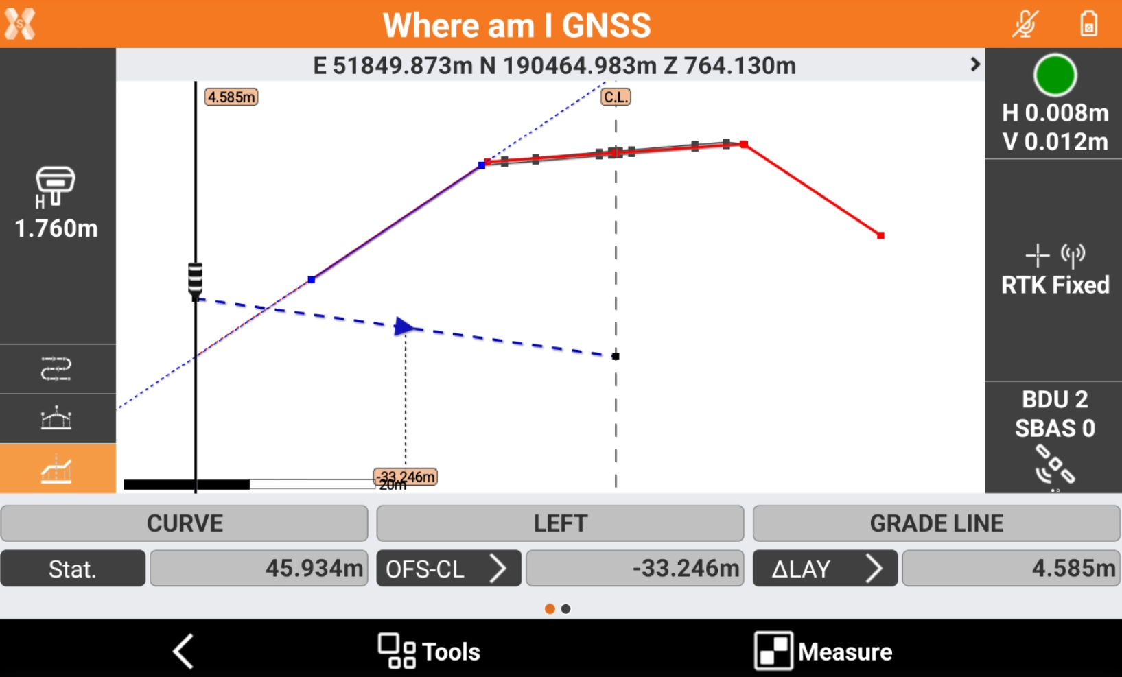
The segment is visible in the graphic view with a blue dotted line.
-
The elevation difference is automatically changed to ∆LAY to display the different elevation to the cross section segment. When outside the segment, the software shows the difference elevation to the extension of the segment.
-
Below video shows how to change the Elevation mode and select a specific segment to stakeout.
Apply an offset
-
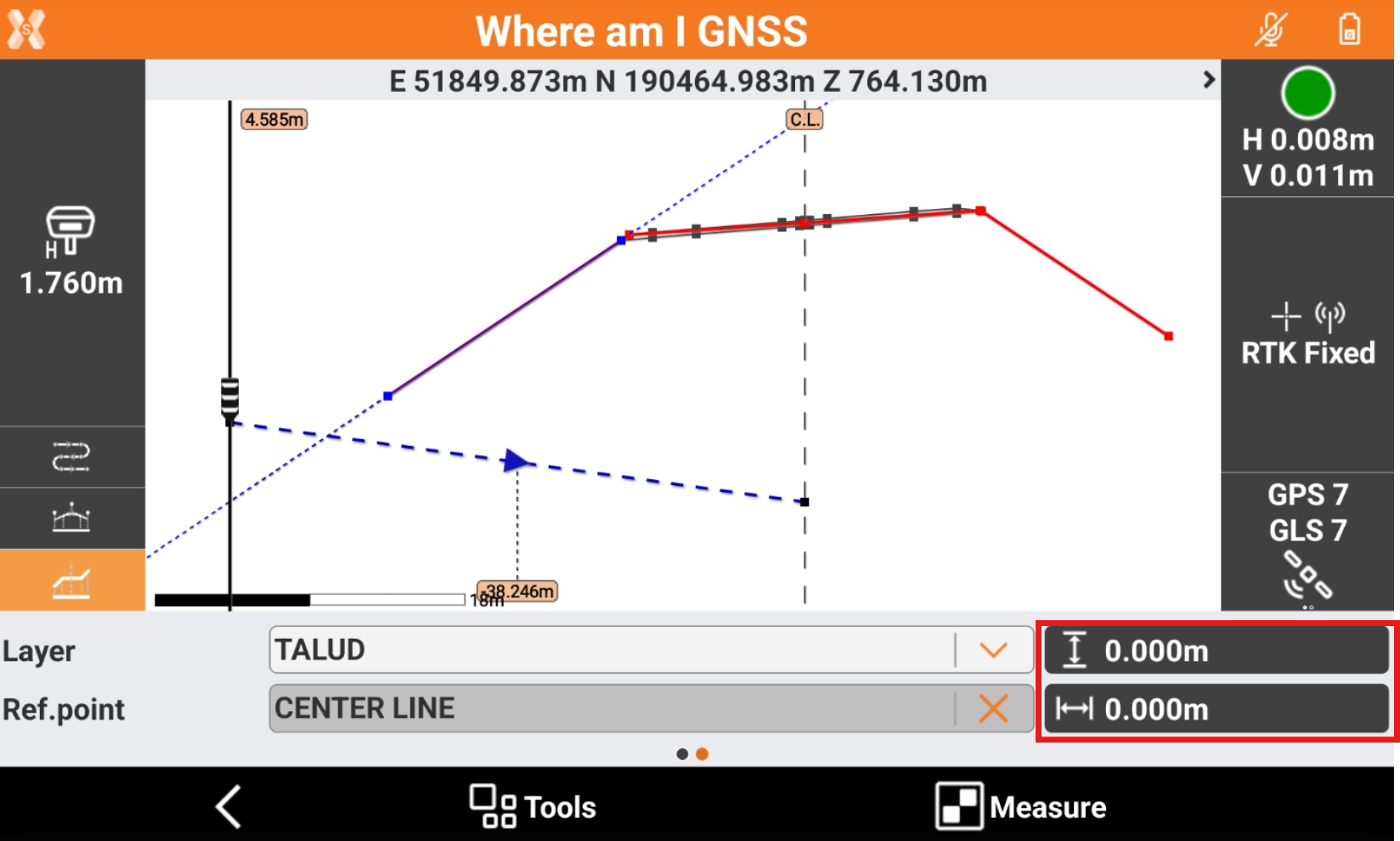
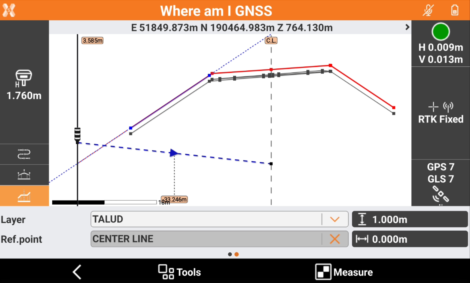
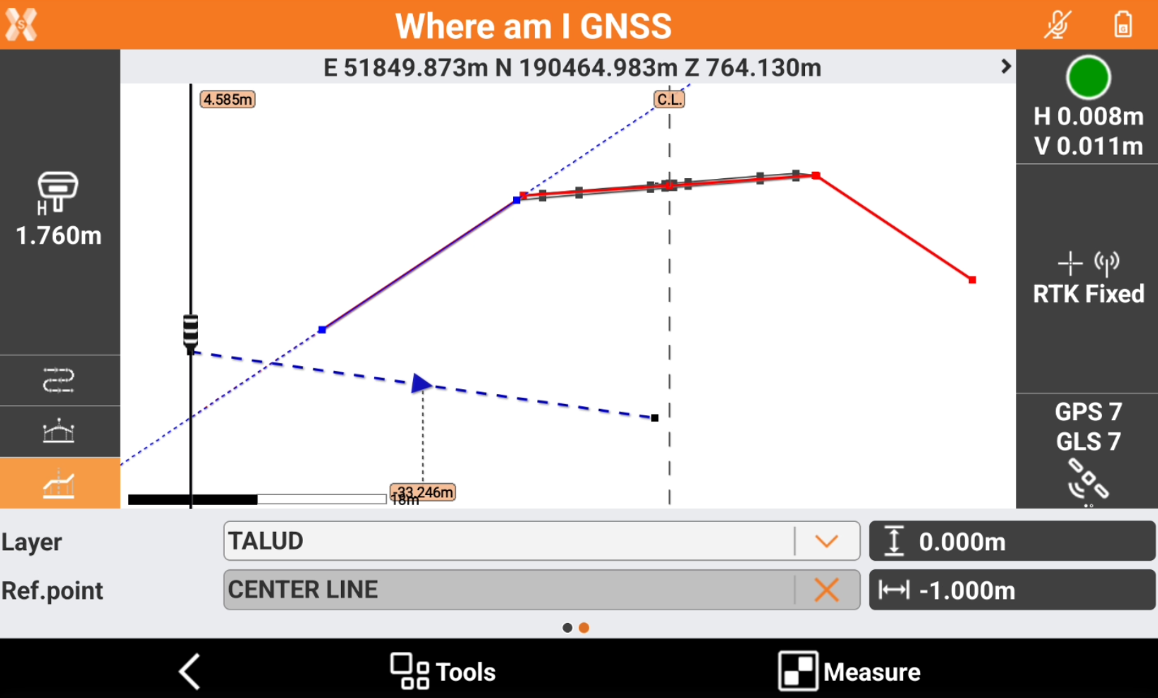
In the application it is possible to apply an horizontal or a vertical offset to the cross section.
-
To apply an offset scroll the toolbar to the right.
-
Select

-
Select

Change road design layer
-
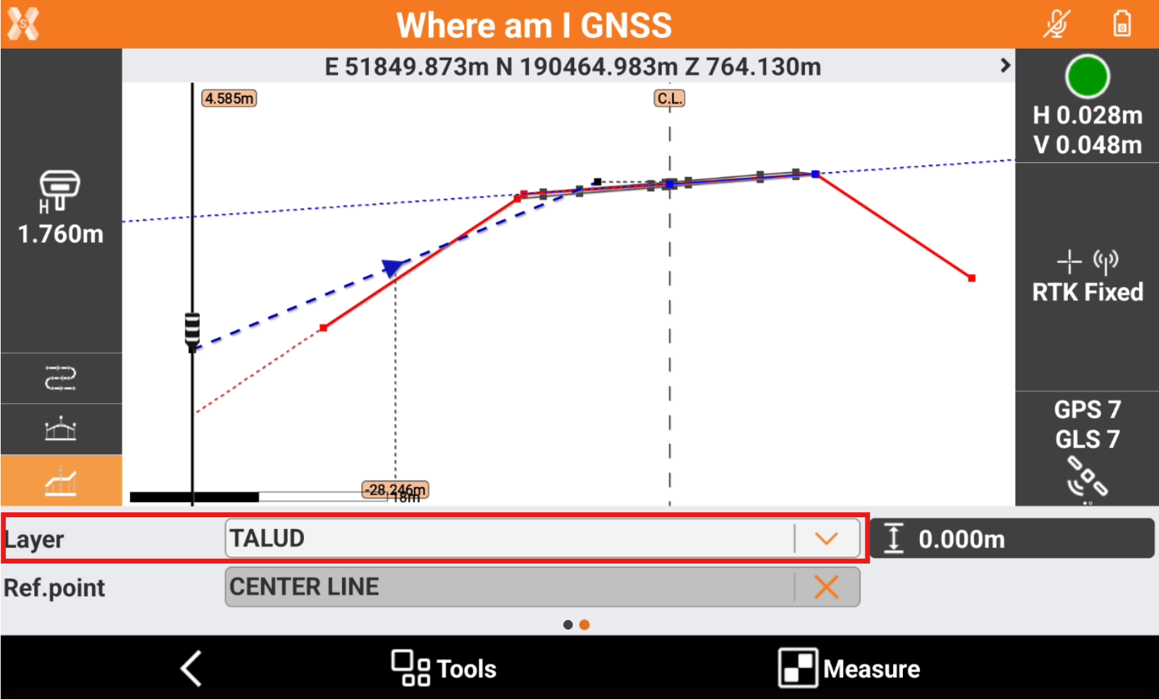
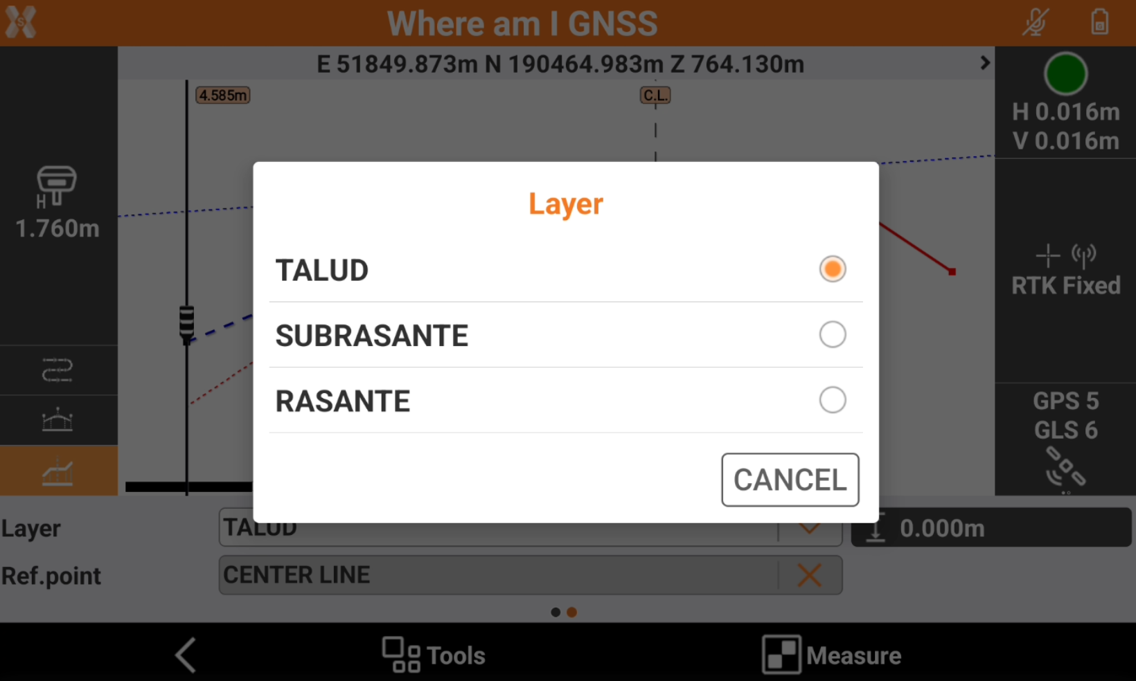
Some data is available with multiple layers.
-
To select a different layer scroll the toolbar to the right and click Layer.
-
Select a different layer to stakeout.
Stakeout elevations on a reference surface
-
It is possible to stakeout elevations using a reference surface. The elevation will be calculated not on the road design but on the reference surface.
-
If a reference surface is used it is possible to change the Elevation mode to SUR and ∆SUR.
-
To load a surface click Tools and select Reference surface.
-
Select a surface from the list of available surfaces.
Measure a point
-
It is possible to record the position with the offset and elevation information.
-
To measure the current position with stakeout information click Measure.
-
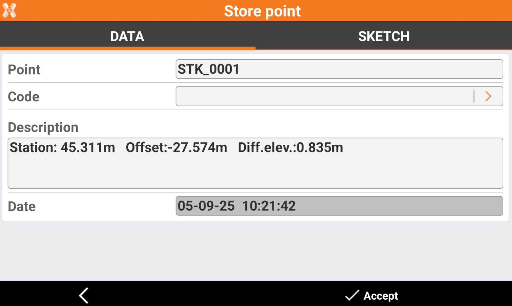
The software records the position, entering the stakeout information in the description.
-
Click Accept to save the point.
-
The recorded point is available to be exported in the stakeout report.