


-
The function Scan plane/surface allows to use the motorized total station to perform an automatic measurement of a plane or a generic surface.
Scan plane
-
Scan plane uses the motorized total station to perform an automatic measurement of a plane (horizontal, vertical or sloped) surface; the reference plane can be also a surface of an IFC model.
-
It is possible to define the area to scan (rectangular or polygonal), the grid size and the software will drive the Total station to measure each single point of the grid.
-
The result of the scan is a colorized grid of points and a 3D surface in which areas out of tolerance are immediately visible; the tolerance can be changed interactively and a new colorized map is generated.
-
To identify the areas out of tolerance in the physical plane, just select a point on the screen and TPS will rotate toward the selected point.
-
Points and surface can be exported (in 3D or plane 2D coordinates) to be used in different ways.
-
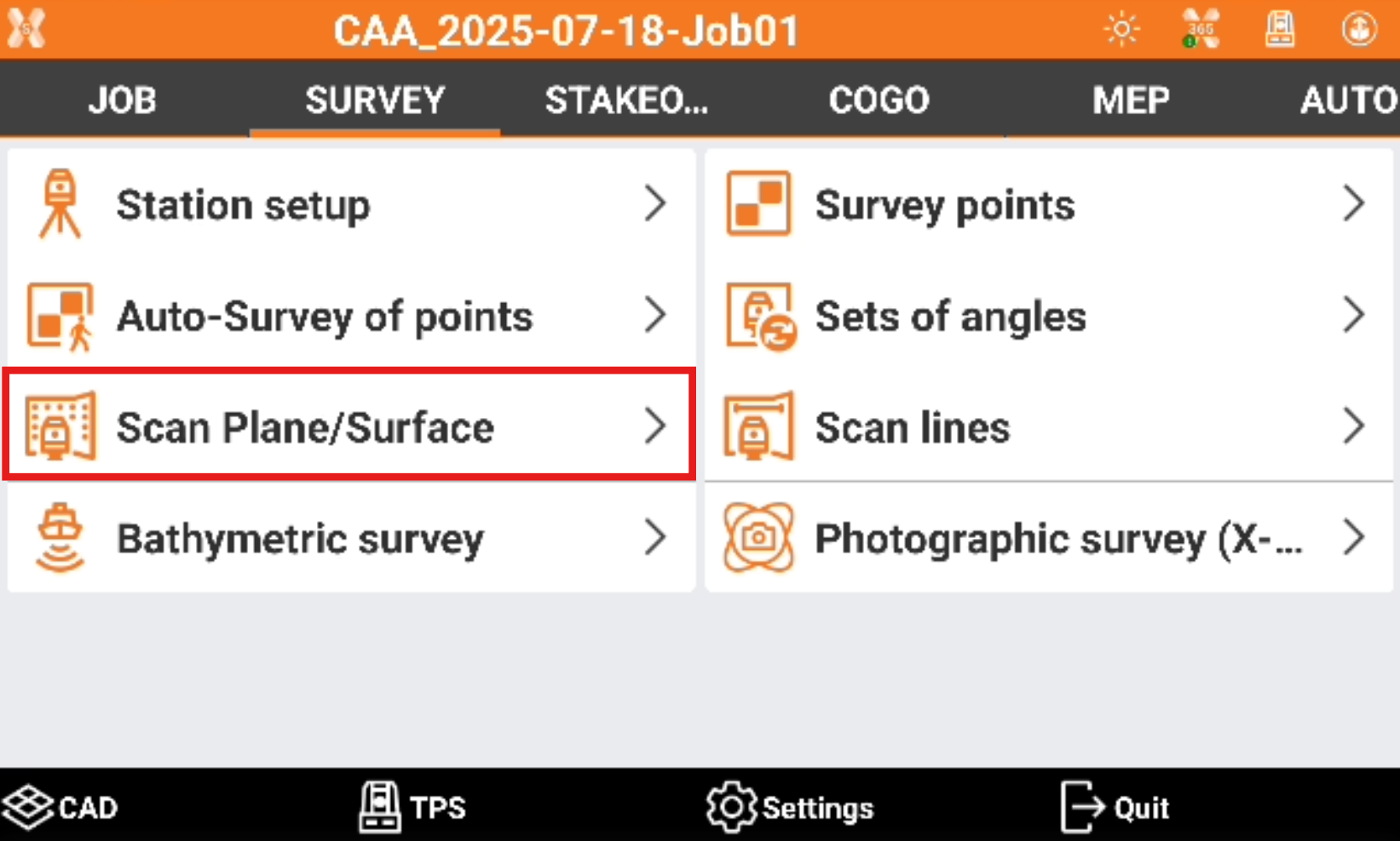
Click Survey.
-
Click Scan plane/surface.
-
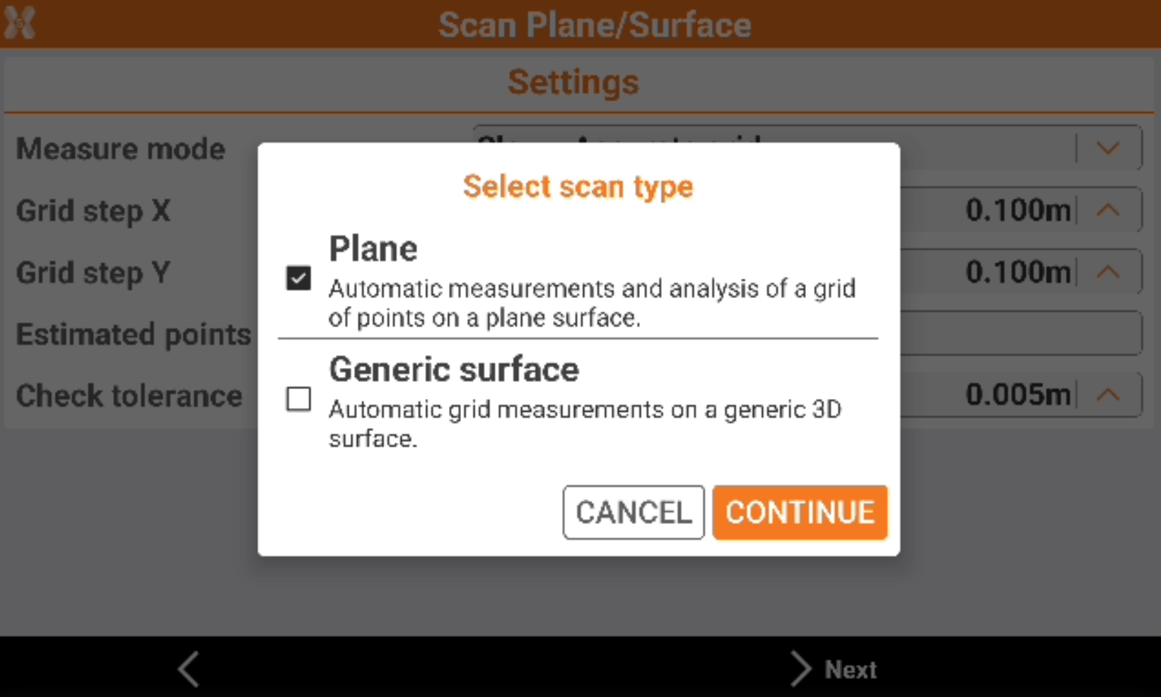
Select Plane.
-
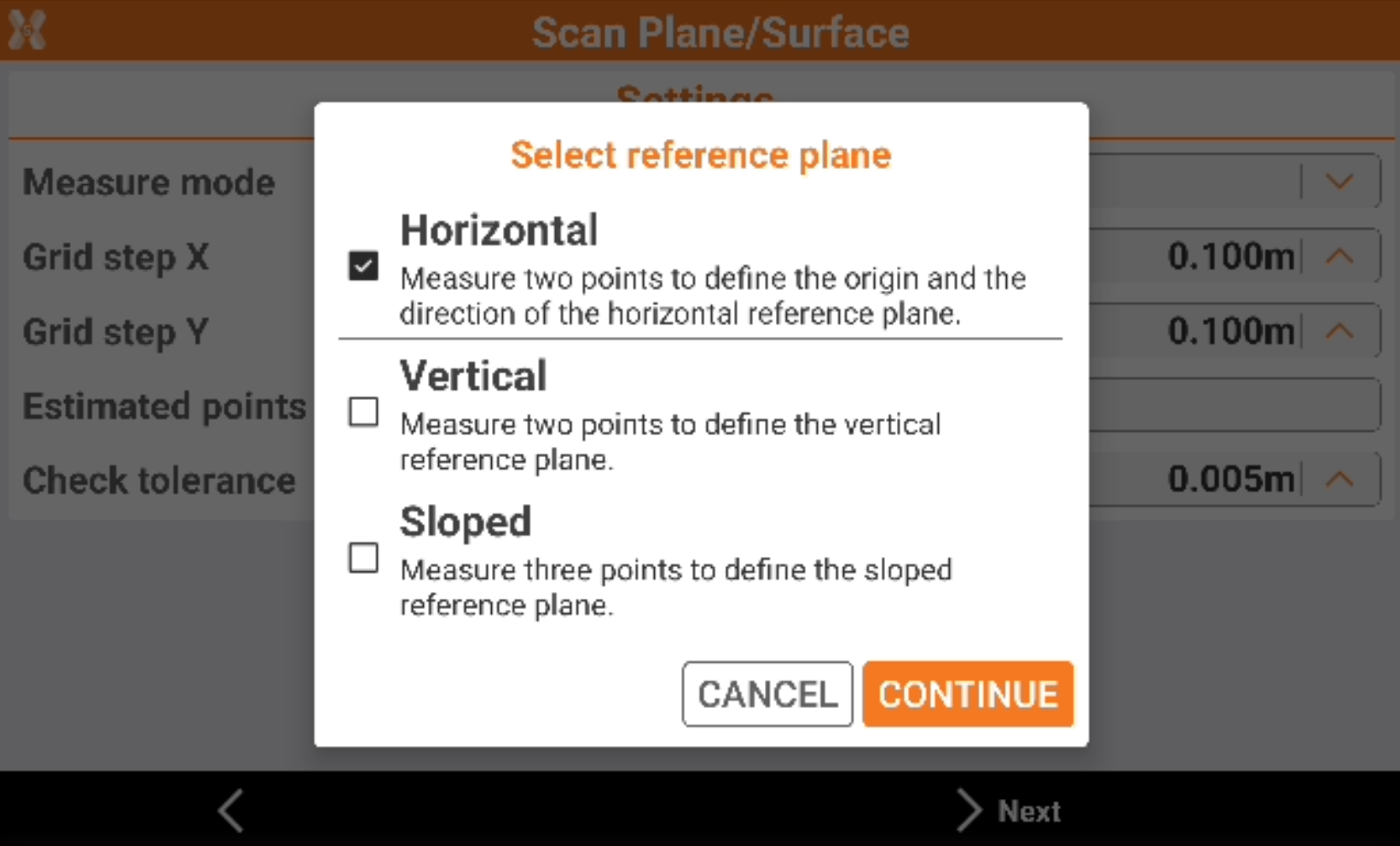
Select the reference plane.
-
Horizontal: the reference plane is horizontal. The plane is defined measuring the origin and the direction of the horizontal reference plane.
-
Vertical: the reference plane is vertical. Two points are measured to define the plane.
-
Sloped: the reference plane is sloped. Three points are measured to define the plane.
-
-
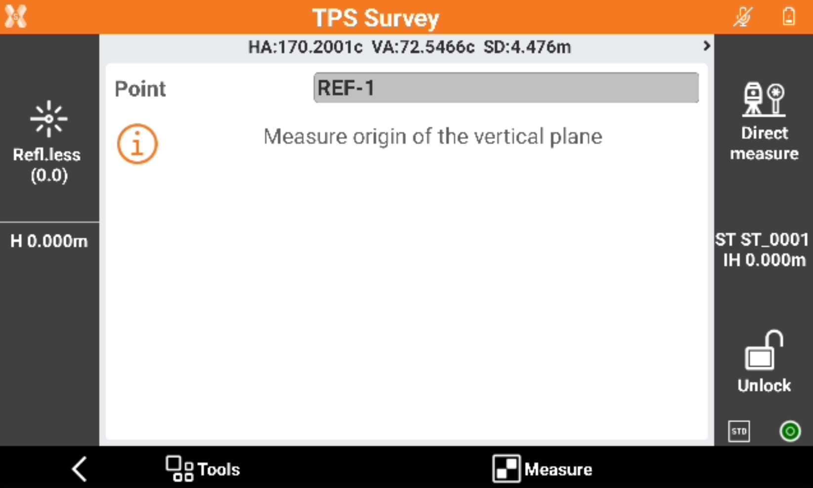
Click Next to define the plane measuring the required reference point.
-
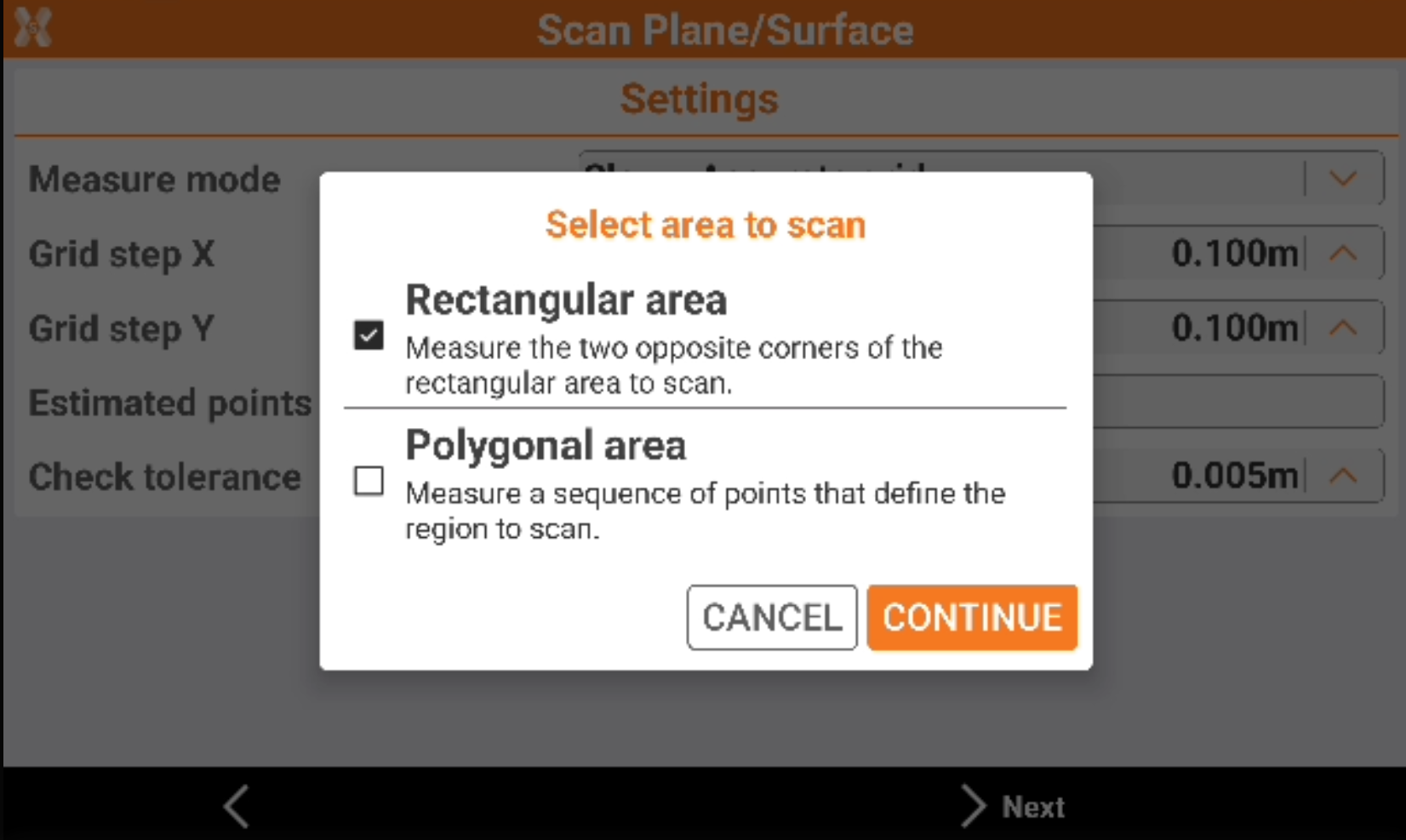
Select the Scan area.
-
Rectangular area: the area to scan is a rectangle defined by measuring the two opposite corners of the rectangle.
-
Polygonal area: the area to scan is defined by measuring a sequence of points.
-
-
Click Next and measure the points to define the scan area.
-
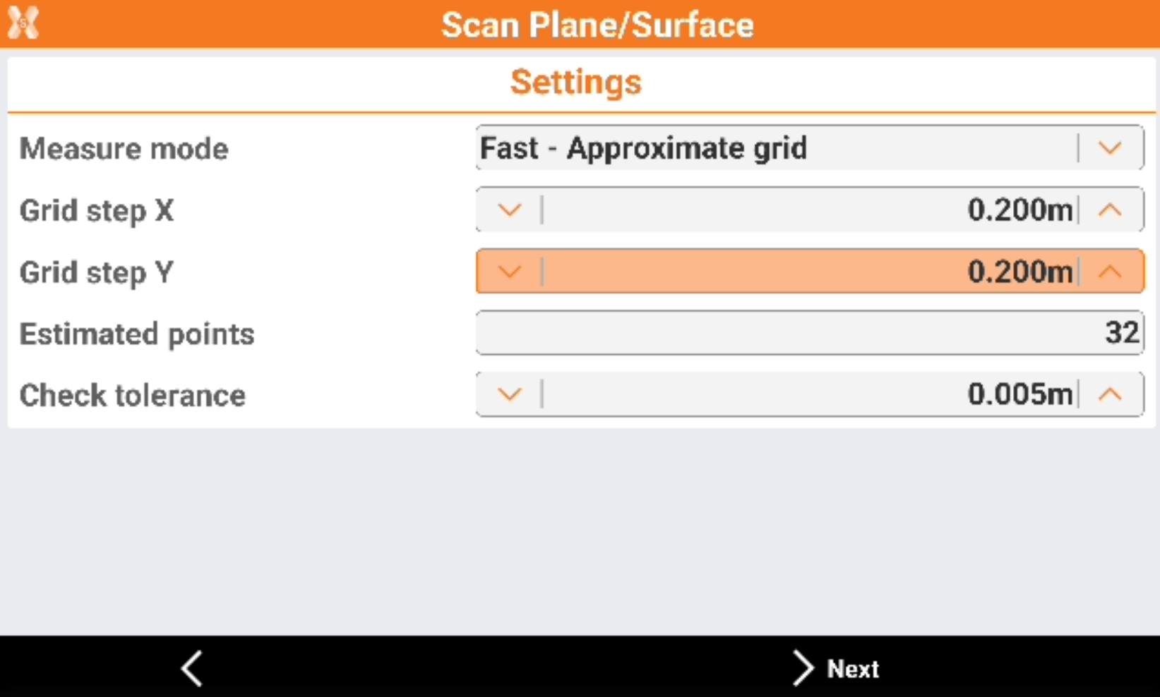
Enter the scan Settings.
-
Measure mode: the scanning measure mode. Slower is the measure mode and more accurate is the distance between the points of the grid.
-
Grid step X: the grid step on the X component.
-
Grid step Y: the grid step on the Y component.
-
Estimated points: number of points that the software estimates to measure based on scan area and grid step.
-
Check tolerance: the tolerance to check for the measured points.
-
-
Click Next and press Start to start the scan.
-
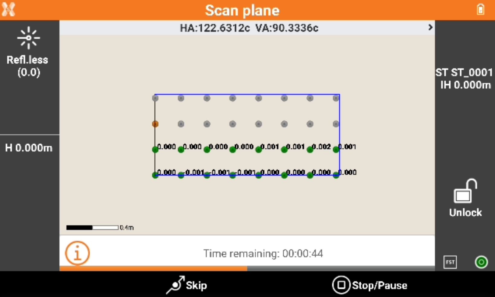
The software shows the grid of the points to measure.
-
Green points: measured points, the difference from the measured coordinate and the coordinate on the defined plane is visualized. The difference is within the tolerance.
-
Red points: measured points, the difference from the measured coordinate and the coordinate on the defined plane is visualized. The difference is over the tolerance.
-
Orange point: the point currently measured.
-
Grey points: the points still not measured.
-
-
Press Skip to skip the measure of the current point.
-
Press Stop/Pause to interrupt or pause the scanning.
-
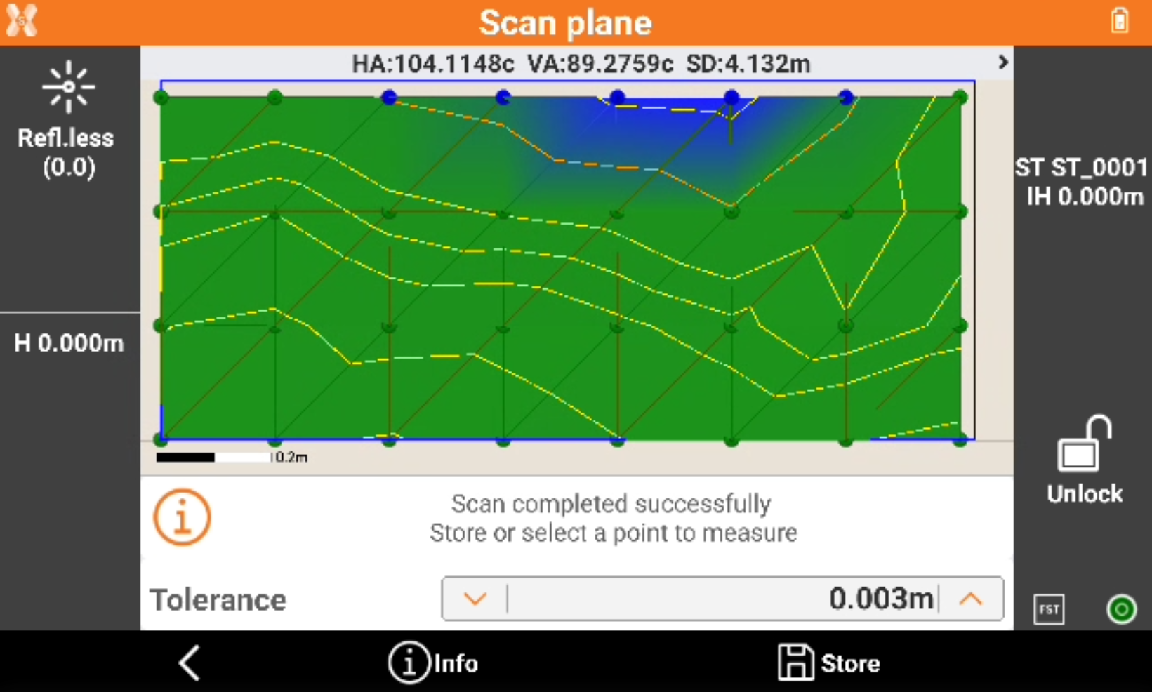
When the scanning is completed the software shows the calculated surface with the contour lines.
-
Click on a point in the graphic view to rotate the instrument to the point. Then click Measure to remeasure the point.
-
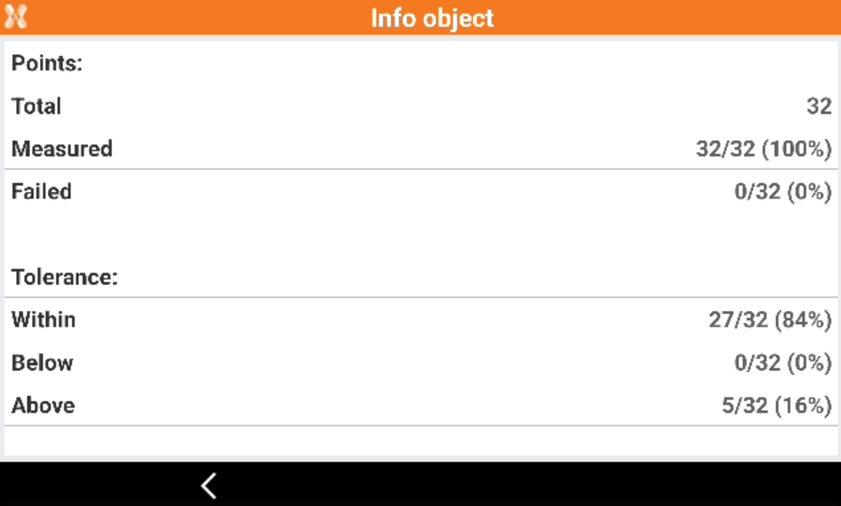
Click Info to open the information of the scanned object.
-
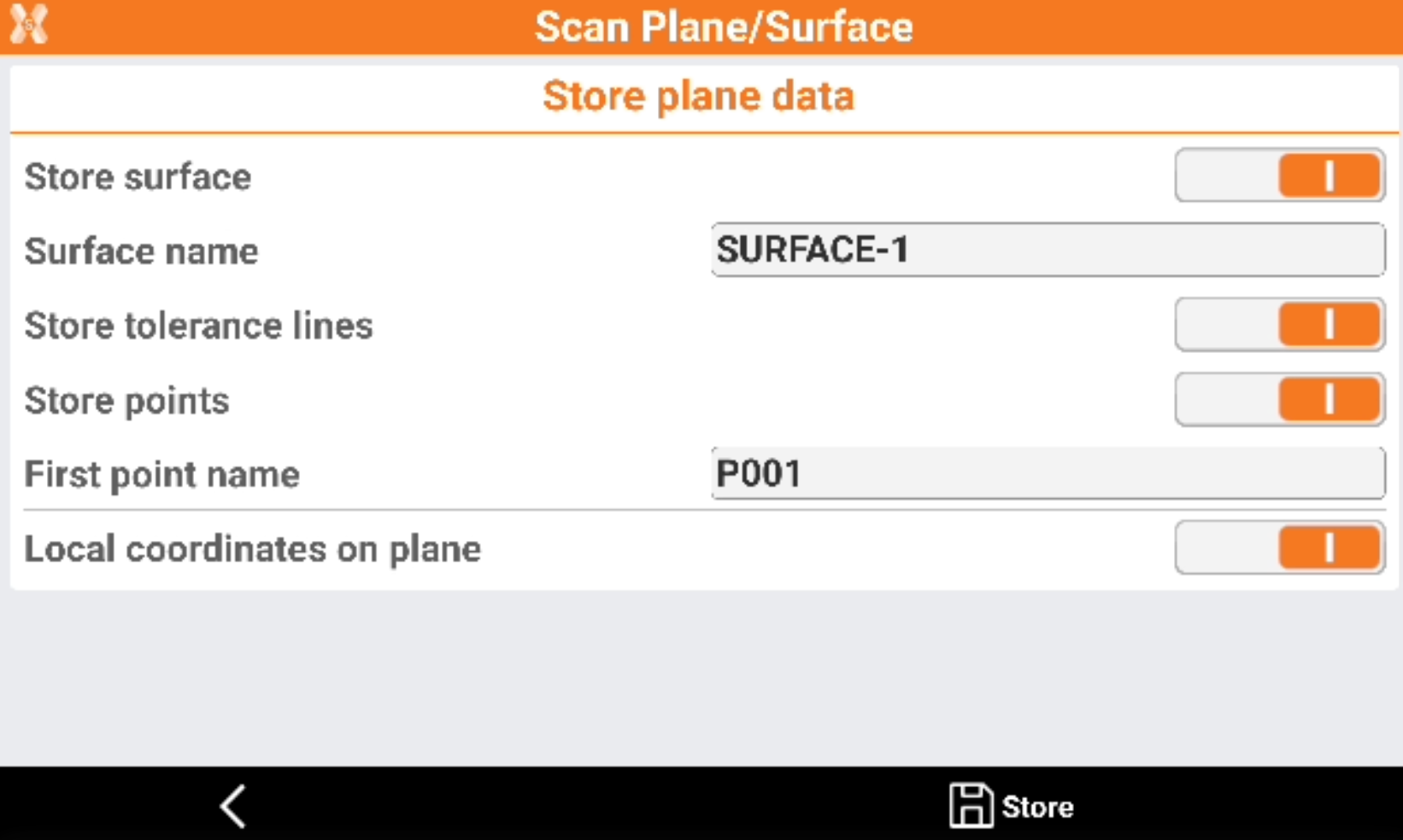
Click Store to store the results.
-
Store surface: allows to store the calculated surface in the current job.
-
Surface name: the name of the surface to store.
-
Store tolerance lines: the tolerance lines are stored in the current job.
-
Store points: all measured points are stored in the current job.
-
First point name: the name of the first stored point. The point name is then automatically increased.
-
Local coordinates on plane: if enabled, the points on the plane are in local coordinates.
-
Scan generic surface
-
Scan surface uses the motorized total station to perform an automatic measurement of a surface.
-
It is possible to define the area to scan (rectangular or polygonal), the grid size and the software will drive the Total station to measure each single point of the grid.
-
The result of the scan is a grid of points and a 3D surface that can be used for further calculations or can be exported to be used in different ways.
-
Click Survey.
-
Click Scan plane/surface.
-
Select Generic surface.
-
Select the Scan area.
-
Rectangular area: the area to scan is a rectangle defined by measuring the two opposite corners of the rectangle.
-
Polygonal area: the area to scan is defined by measuring a sequence of points.
-
-
Click Next and measure the points to define the scan area.
-
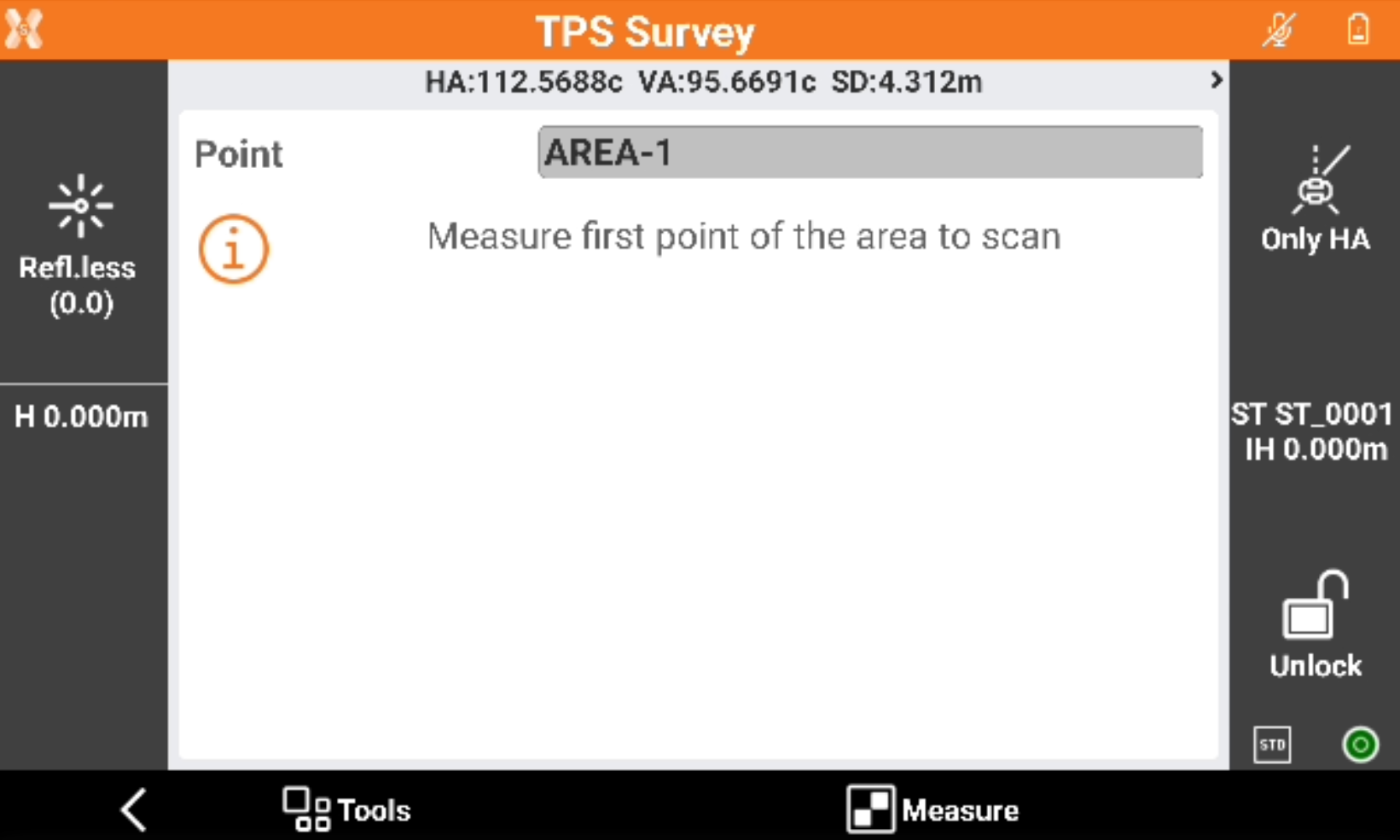
Measure the points that define the area to scan. Click Back to complete the definition.
-
Measure a point that defines the average distance of the surface from the instrument.
-
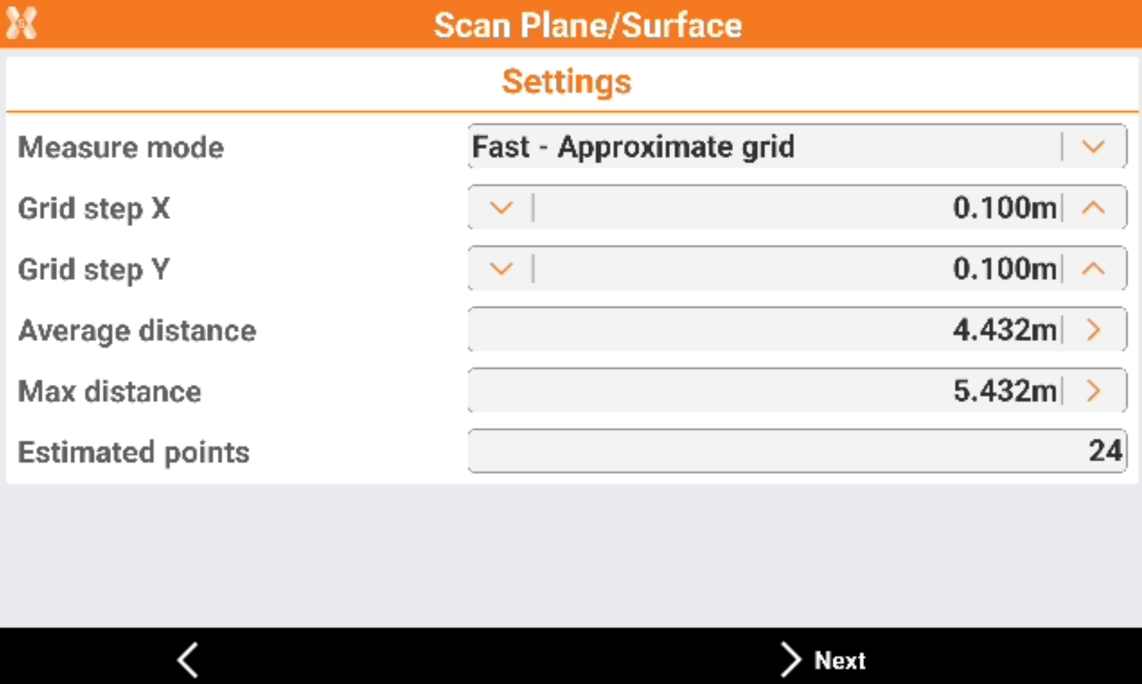
Enter the scan Settings.
-
Measure mode: the scanning measure mode. Slower is the measure mode and more accurate is the distance between the points of the grid.
-
Grid step X: the grid step on the X component.
-
Grid step Y: the grid step on the Y component.
-
Average distance: the average distance from the instrument to the surface to scan.
-
Max distance: the maximum distance from the instrument to the surface to scan.
-
Estimated points: number of points that the software estimates to measure based on scan area and grid step.
-
-
Click Next and press Start to start the scan.
-
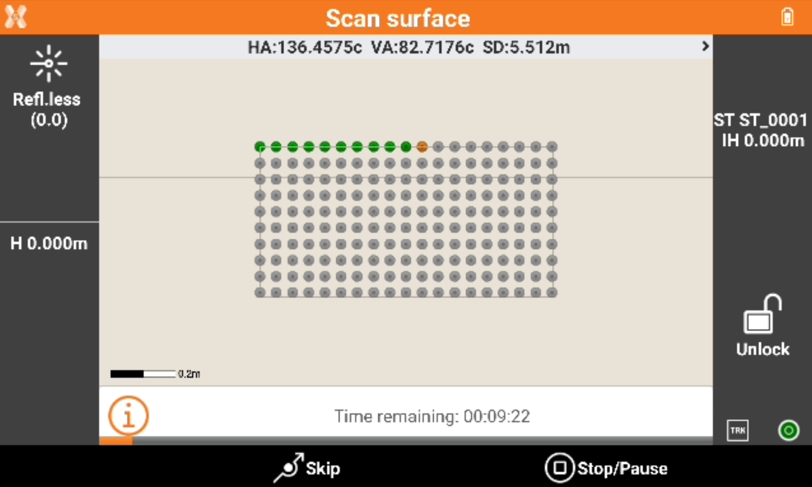
The software shows the grid of the points to measure.
-
Green points: measured points,.
-
Orange point: the point currently measured.
-
Grey points: the points still not measured.
-
-
Press Skip to skip the measure of the current point.
-
Press Stop/Pause to interrupt or pause the scanning.
-
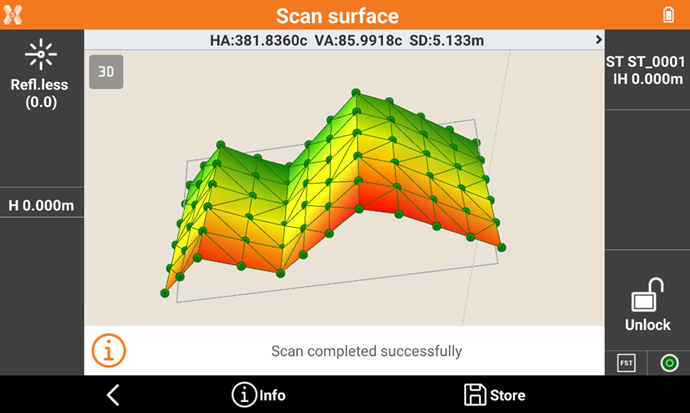
When the scanning is completed the software shows the calculated surface with the contour lines.
-
Click on a point in the graphic view to rotate the instrument to the point. Then click Measure to remeasure the point.
-
Click Info to open the information of the scanned object.
-
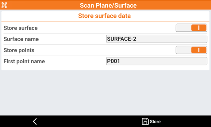
Click Store to store the results.
-
Store surface: allows to store the calculated surface in the current job.
-
Surface name: the name of the surface to store.
-
Store points: all measured points are stored in the current job.
-
First point name: the name of the first stored point. The point name is then automatically increased.
-