


-
The system is created based on the measurement of a point of origin and the measurement of a two points which defines the direction of the two axis.
-
From GNSS localization select Two reference axis.
-
The procedure requires to measure 2 points on the 2 reference axis, and then identify these 2 axis in CAD.
-
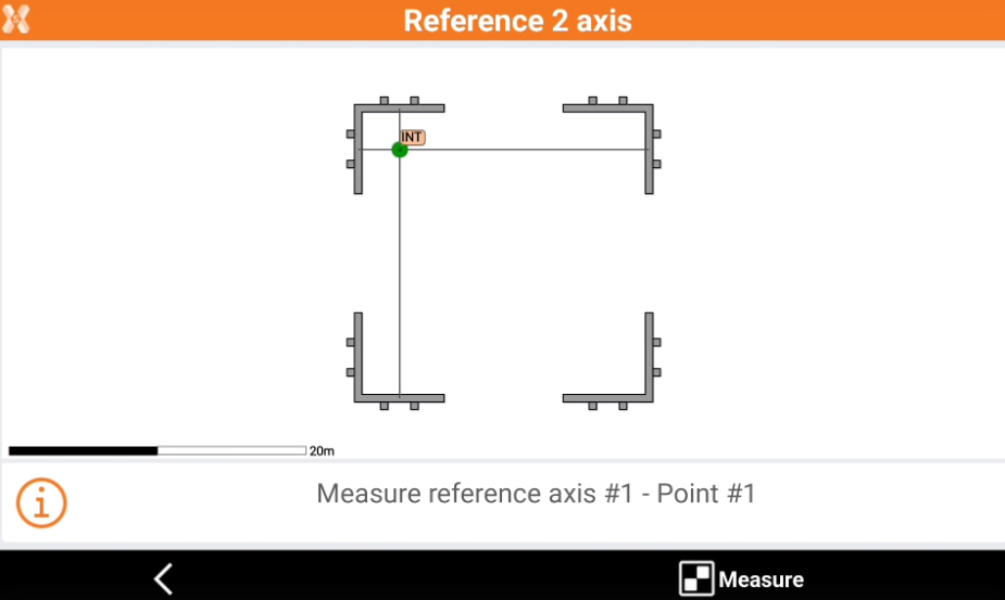
Click Measure to measure the first point on the first reference axis.
-
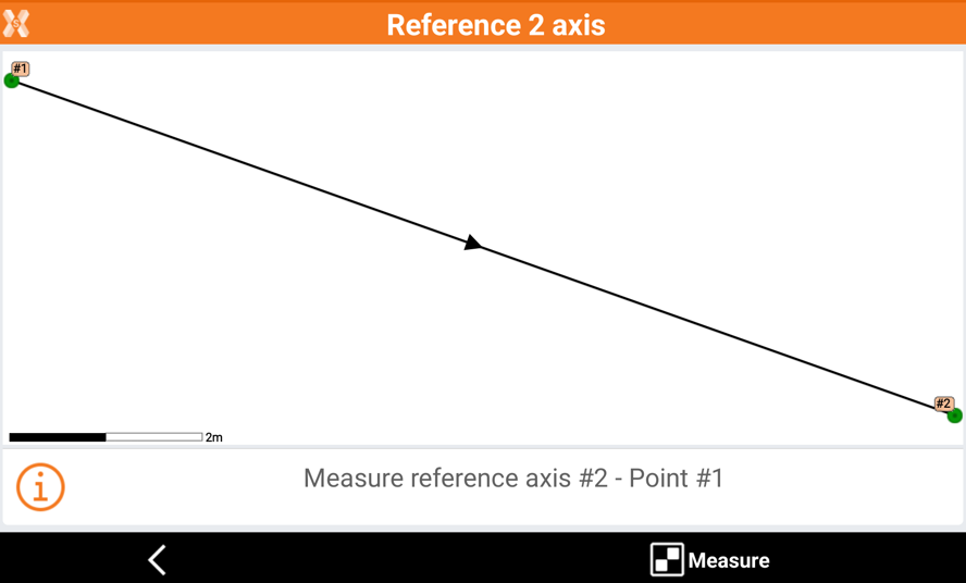
Click Measure again to measure the second point of the first reference axis.
-
The software shows on video the first measured reference axis.
-
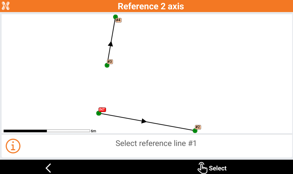
Click Measure and proceed to measure 2 points on the second reference axis.
-
The software shows the 2 measured reference axis.
-
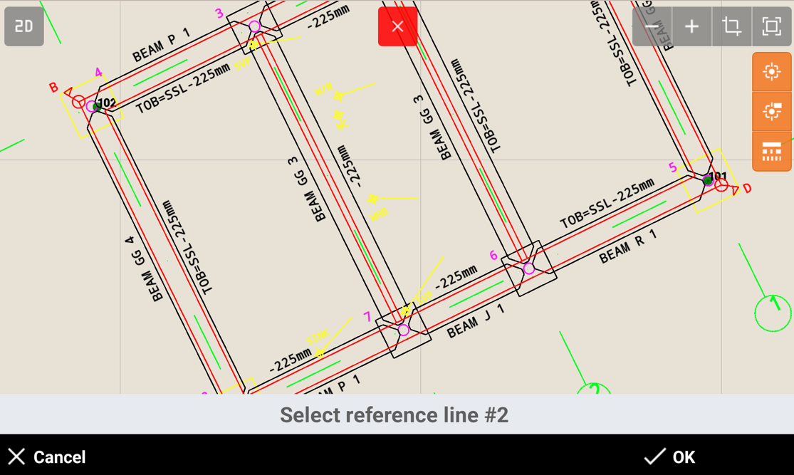
Click Select to select the 2 measured reference axis in CAD, selecting reference line 1 and reference line 2.
-
Click OK to calculate the local system.
-
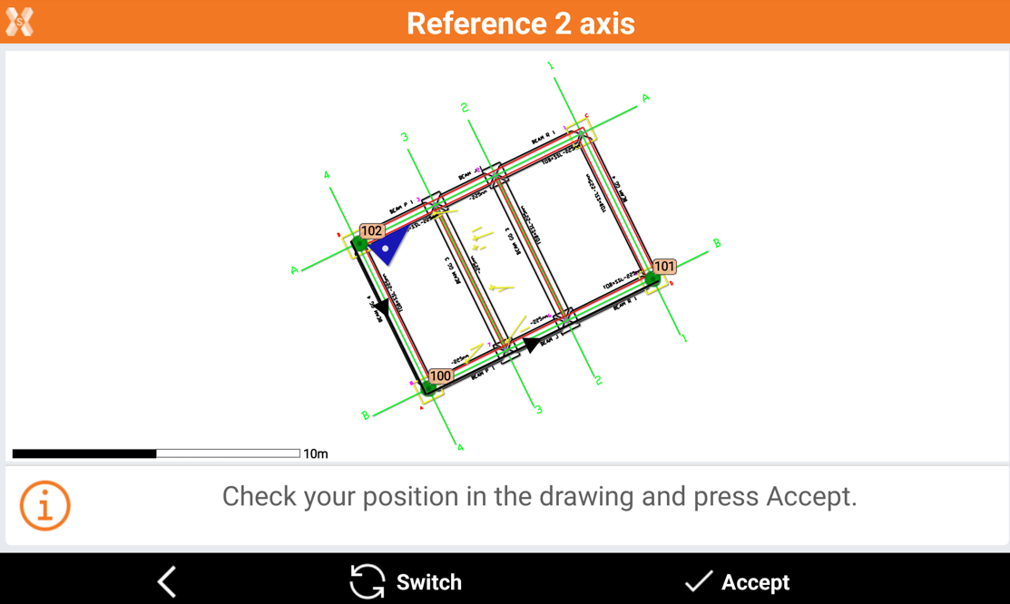
Check the GNSS position in the drawing, if it is correct.
-
Click Switch in case position in not correct, to switch the axis, or click Accept to accept the system.
-
Select the calculation method to be used for elevation and click Accept.