
-
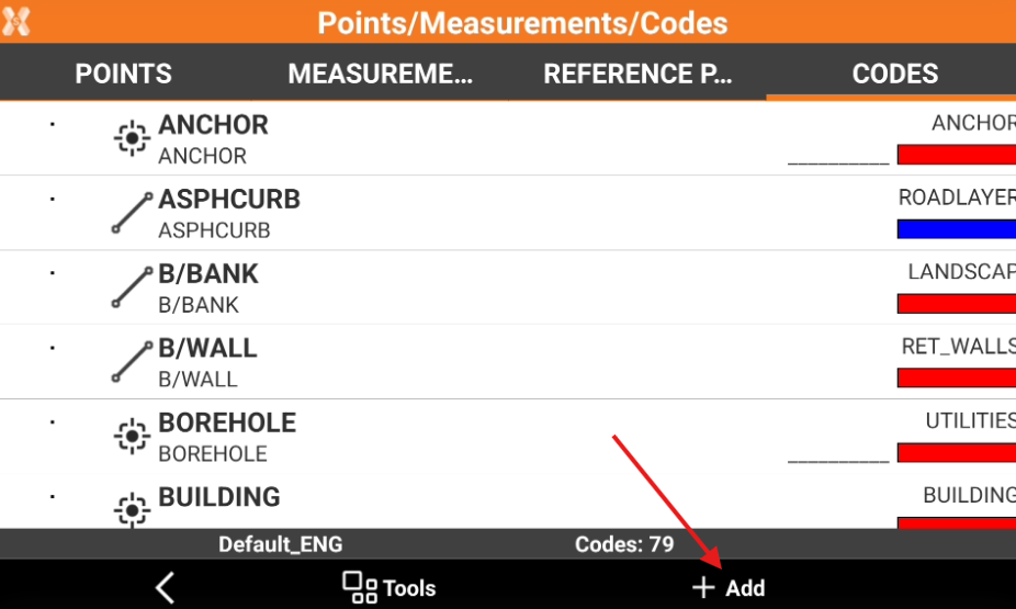
To create a new code from the Survey codes page click Job.
-
Click Points/Measurements/Codes.
-
Open the Codes tab.
-
Click Add.
-
The data of the code is organised in pages.
Main data page
-
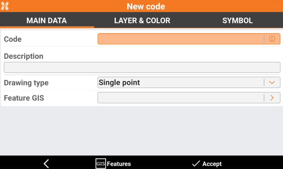
This page allows to enter code name, description and drawing type.
-
Code: name of the code. For a parametric codes use symbol # in code name to pass a value from code name to description automatically. For example code “D#” and description “Distance #cm”: entering in application code “D25” will result in description “Distance 25cm”.
-
Description: extended description.
-
Drawing type: defines how the measured object is shown in graphics.
-
Single point: a single position is used, for example for a tree or an illumination pole.
-
Line: a polyline is used, for example for the side of a road or a wall.
-
Square diagonal: a square is used inserted at the opposite end of the measured point.
-
Square center: a square is used inserted at the centre of the measured object or in the middle of a measured line.
-
Rectangle base: a rectangle is used inserted at the opposite end of the measured point of the base and a point on the opposite side.
-
Rectangle center: a rectangle is used inserted at the centre, the middle point on a side and a third point on the other side.
-
Circle 3P: a circle is used inserted by measuring three points on the circumference.
-
Circle center: a circle is used inserted by measuring the center point and a point on the circumference.
-
Spline: a spline is used.
-
Control point: a control point measurement is used.
-
-
GIS features: one of the GIS features from the current job can be assigned to the point. More information can be added defined by the properties of the associated GIS feature.
-
Layer & color page
-
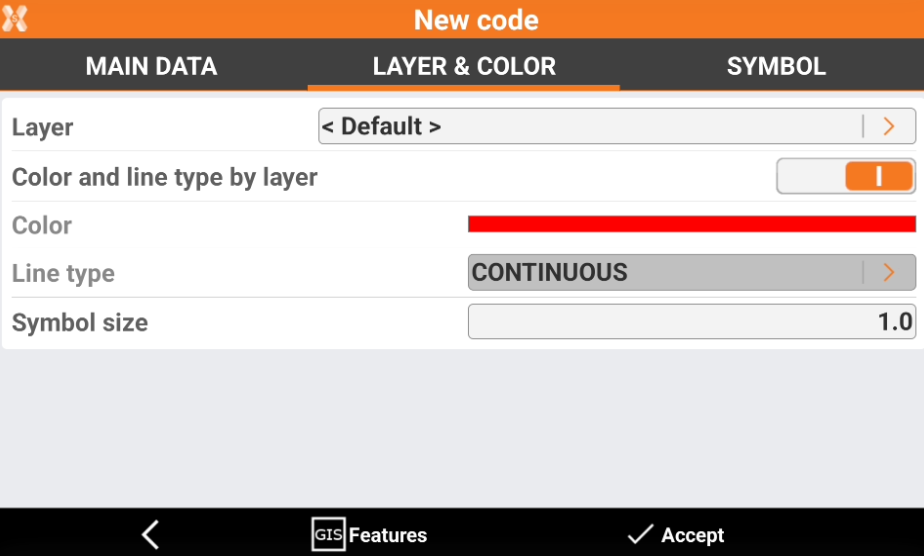
These are the settings for the single layer. When creating a layer, the default settings saved in the main Settings page are displayed. The settings here can be changed.
-
Layer: layer linked to point.
-
Color and line type by layer: the color and line type of the layer is used for the drawing of the point symbol and its line type.
-
Color: color used for the point symbol if the layer color is not used.
-
Line type: line type used if the line type by later is not used.
-
Symbol size: dimension of the symbol.
-
-
Click on the arrow near the Layer to open the Layer manager.
-
Click on the arrow near the Line type to open the Line types manager.
-
Click GIS Features button to open the GIS features manager.
Symbol
-
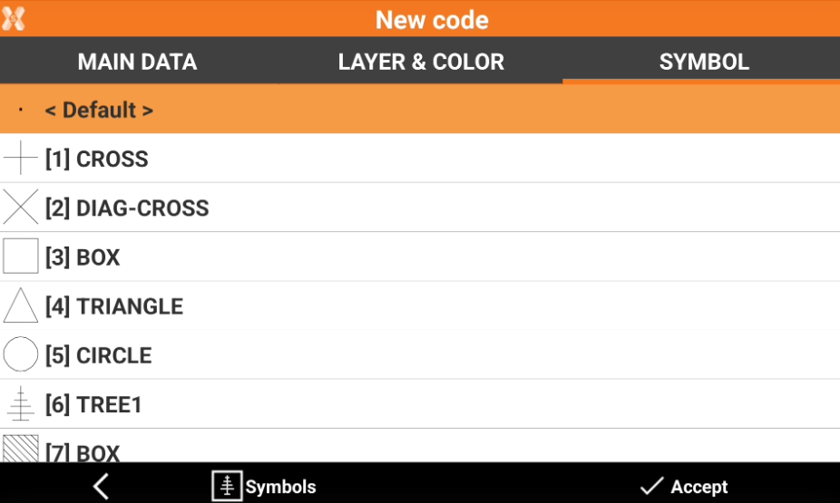
This page allows to assign a symbol to a code. It is possible to use default symbols or import new symbols from DWG file.
-
Select a symbol used to draw the point to which the code is associated from the list.
-
Click Symbols button to open the Symbols manager and importing new symbols.